High-pressure rotary jet drilling machine capable of achieving directional swing jet at any azimuth angle and construction method

An arbitrary orientation, high-pressure rotary spraying technology, applied in soil protection, foundation structure engineering, sheet pile walls, etc., can solve problems such as difficult pile formation, fan-shaped pendulum spraying, and failure to form, and achieves convenient parameter setting and automation. High, good pile-forming effect

Inactive Publication Date: 2020-02-18
南京同力建设集团股份有限公司
View PDF5 Cites 1 Cited by
  • Summary
  • Abstract
  • Description
  • Claims
  • Application Information

AI Technical Summary

Problems solved by technology

Once the reverse rotation occurs, the threaded connection between the drill pipe and the drill pipe will fall off and cannot work normally
Moreover, after the multi-section drill pipes are connected, the spraying direction of the nozzle is not easy to keep consistent with the initial spraying direction, which makes the "alignment" of the pendulum spraying construction very difficult and rough, and it is difficult to form piles according to the design requirements
At the same time, the existing ordinary high-pressure rotary grouting drilling rigs do not have the functions of intermittent lifting and orientation at any azimuth angle, and cannot form fan-shaped pendulum spraying at any angle, which is difficult to meet the construction requirements

Method used


Image

  • High-pressure rotary jet drilling machine capable of achieving directional swing jet at any azimuth angle and construction method
  • High-pressure rotary jet drilling machine capable of achieving directional swing jet at any azimuth angle and construction method
  • High-pressure rotary jet drilling machine capable of achieving directional swing jet at any azimuth angle and construction method

Examples


Embodiment Construction

[0026] The present invention will be further described below in conjunction with the accompanying drawings and embodiments.

[0027] Such as Figure 1 to Figure 5 shown.

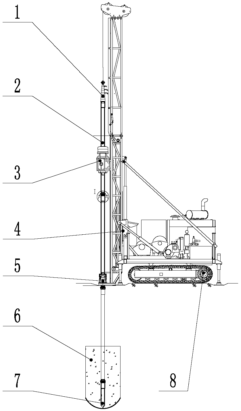
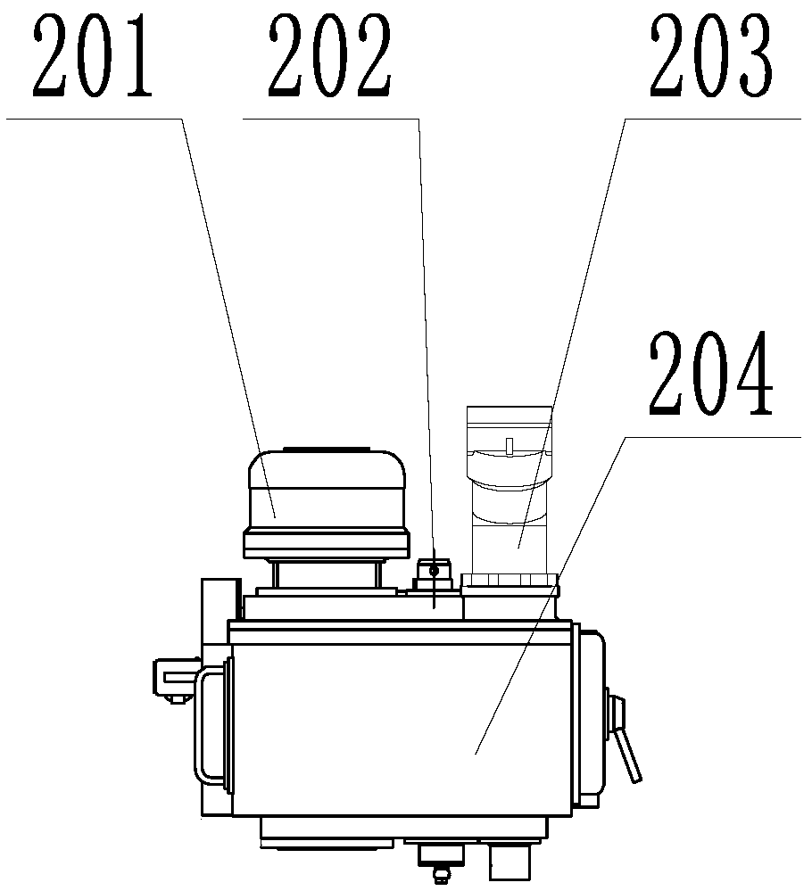
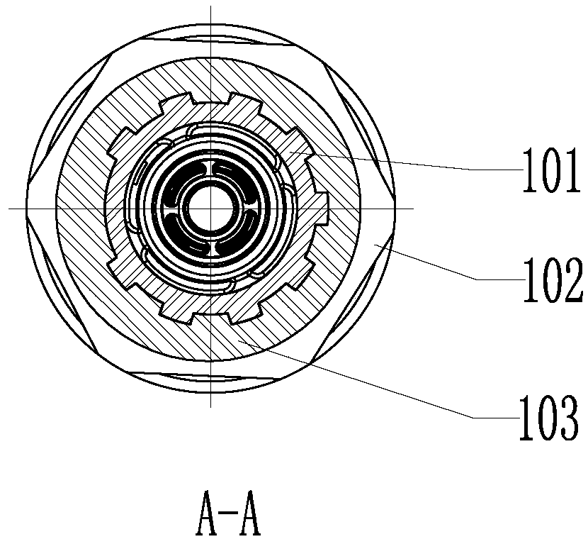
[0028] A high-pressure rotary jet drilling rig capable of directional pendulum spraying at any azimuth angle, driven by a full hydraulic system, including a fuselage 8, a deflector 1, a power head 3, a drill pipe 2, a drill pipe holder 5 and a sliding frame assembly into 4. The slewing and lifting drive of the power head 3 adopts an electric proportional control hydraulic load sensing pressure flow compensation system. The power head 3 includes a drill pipe rotary drive, a motor and a gearbox. Wherein, the motor is a high-speed quantitative plunger motor; the hydraulic system is equipped with an electric proportional control closed-center load sensing multi-way reversing valve, a load sensing control variable plunger variable pump and a hydraulic cylinder. The reversing valve is connected with the indust...


PUM


Abstract

The invention relates to a high-pressure rotary jet drilling machine capable of achieving directional swing jet at any azimuth angle and a construction method. The high-pressure rotary jet drilling machine comprises a power head and a drill rod, wherein a multi-circle absolute value encoder I is mounted on a driving shaft of a final driving stage of the drill rod on the power head; a sliding frameassembly is arranged on the drill rod; a multi-circle absolute value encoder II is arranged on the sliding frame assembly; the multi-circle absolute value encoder I and the multi-circle absolute value encoder II are connected with an industrial personal computer through CAN buses; and the drill rod is in a multi-section type, and all sections of the drill rod are connected through positioning connecting assemblies, so that the positions of all the sections of the drill rod are kept consistent. According to the high-pressure rotary jet drilling machine, parameter setting is convenient, the automation degree is high, a swing jet starting point and a swing jet returning point CAN be selected at will according to construction requirements, different modes such as continuous rotary jet, continuous swing jet, fixed-point rotary jet, fixed-point swing jet and continuous fixed jet are obtained, the swing jet direction and angle are still kept after the number of the drill rod is increased ordecreased, and swing jet motion is reliably transmitted.

Description

technical field [0001] The invention relates to building construction equipment and a construction method thereof, in particular to a high-pressure jet-jet drilling machine and a construction method thereof, in particular to a high-pressure jet-jet drilling machine capable of directional pendulum spraying at any azimuth and angle and a construction method thereof. Background technique [0002] The jet grouting method uses a high-pressure rotary jet drilling rig as the main construction equipment. During construction, it is necessary to use a drilling rig to drill into the hole first, then insert a special grouting drill pipe or use the power head of the drilling rig to drill the drill pipe with grouting function to the predetermined depth of the soil layer; Slurry, water and high-pressure air are ejected from the nozzle on the drill bit, forming a jet flow to impact and destroy the soil layer; while cutting the soil layer with high-pressure cement slurry (water), slowly use ...

Claims


Application Information

Patent Timeline
Patent Type & Authority Applications(China)
IPC IPC(8): E02D5/46E02D3/12
CPCE02D3/12E02D5/46
Inventor 徐庆平宋炳锐马娟汪宏陈伟明孙本华徐玉桂姚芃
Owner 南京同力建设集团股份有限公司
Why Eureka
Try Eureka