Manipulator device for square bar transferring

A manipulator and square rod technology, applied in manipulators, program-controlled manipulators, grinding machine parts, etc., can solve the problems of increasing the removal allowance of silicon rods, increasing processing time, affecting processing efficiency, etc., and achieving protection from mechanical Damage, Accuracy Improvement, Wide Range of Effects

Pending Publication Date: 2020-02-21
QINGDAO GAOCE TECH CO LTD
View PDF0 Cites 0 Cited by
  • Summary
  • Abstract
  • Description
  • Claims
  • Application Information

AI Technical Summary

Problems solved by technology

During the grinding process, the silicon rod needs to be clamped and transferred. During the transfer process, if the deviation of the silicon rod is large, the removal allowance of the silicon rod during the grinding process will be increased, the processing time will be increased, and the processing efficiency will be seriously affected. , may result in waste rod

Method used


Image

  • Manipulator device for square bar transferring
  • Manipulator device for square bar transferring
  • Manipulator device for square bar transferring

Examples


Embodiment 1

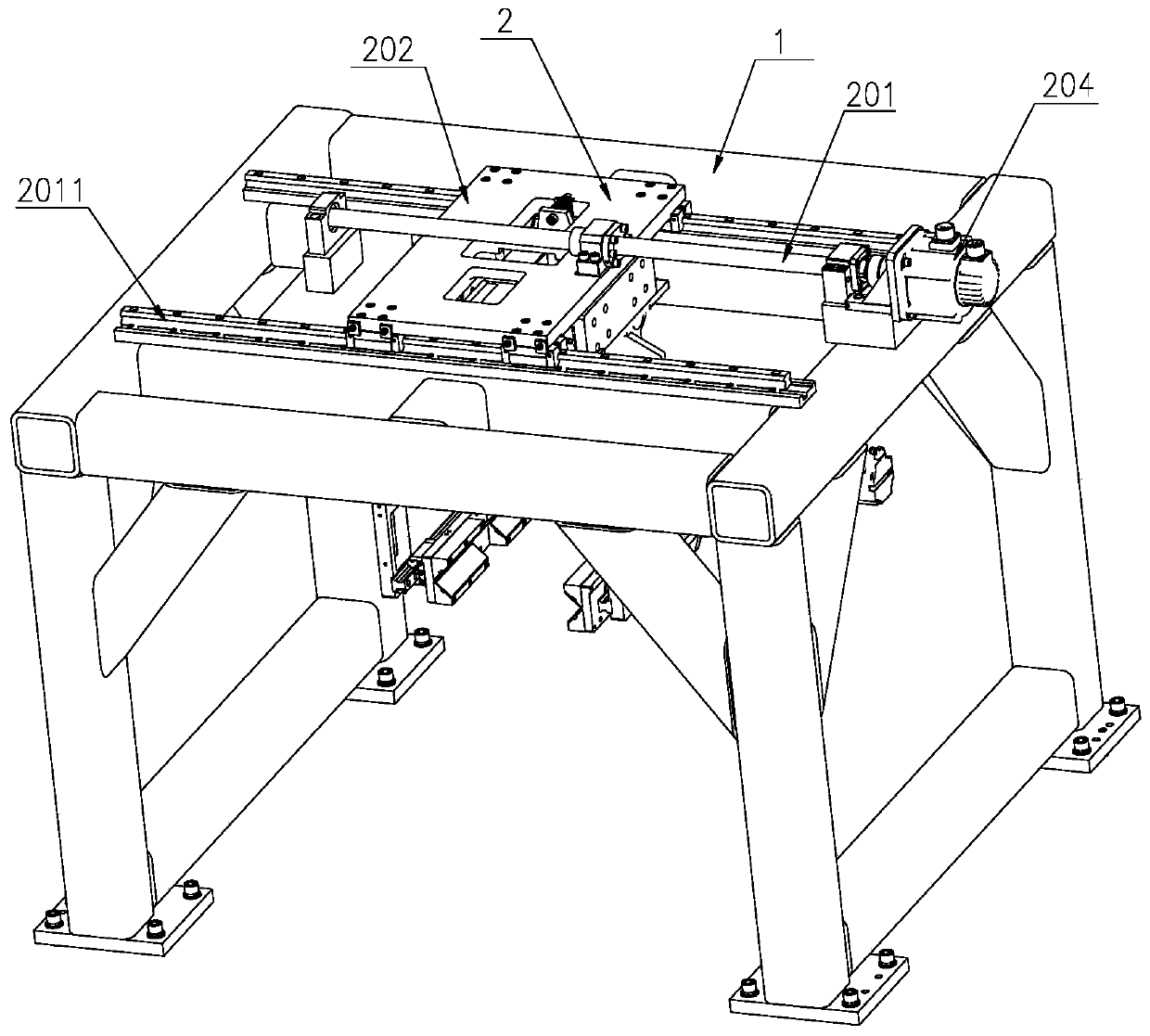
[0033] refer to figure 1 , figure 2 , the grip bracket assembly 2 includes a first lead screw 201, a grip fixing plate 202 and a relay motor 204, the first lead screw 201 is arranged along the Y-axis direction, and its two ends are fixed by the first lead screw 201 It is fixedly connected with the upper part of the transfer frame 1, and the two sides of the first lead screw 201 are respectively provided with first slide rails 2011 to cooperate with the first lead screw 201, and the two ends of the first slide rail 2011 are connected with the transfer The frame 1 is fixed, and the first sliding rail 2011 is arranged parallel to the first lead screw 201 . The handle fixing plate 202 is fixedly connected with the first lead screw 201, and is slidably connected with the transfer frame 1 through the first lead screw 201, and the output end of the transfer motor 204 is connected with one end of the first lead screw 201 to drive the first lead screw 201. Bar 201 Movement. Two sub...

Embodiment 2

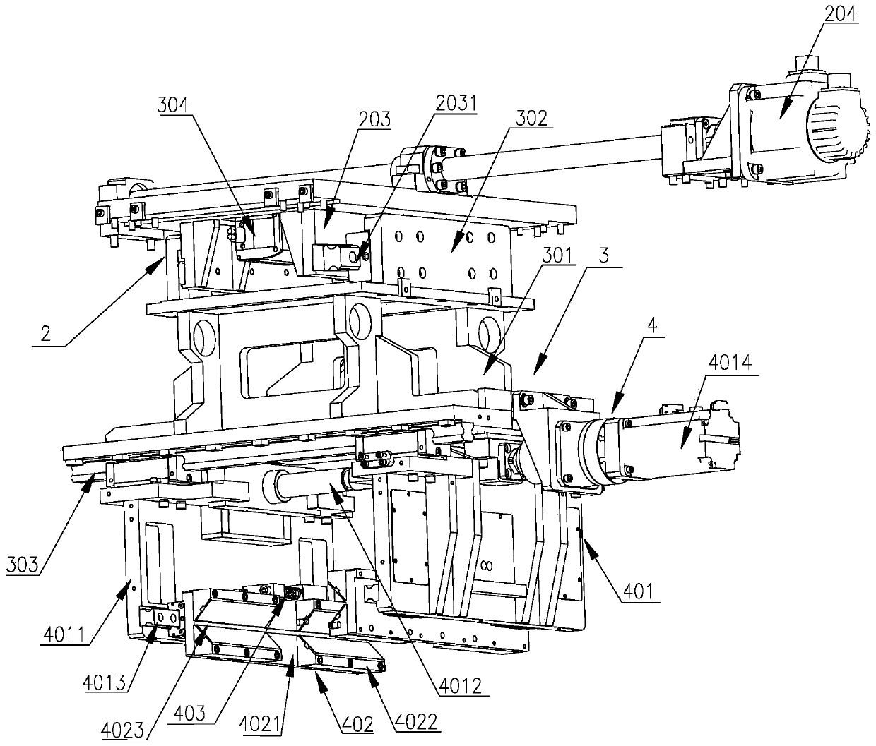
[0037] refer to figure 1 , figure 2 and image 3, the square bar clamping unit 4 includes a push plate assembly 401, a square bar fixing assembly 402 and a buffer assembly 403, the upper part of the push plate assembly 401 is slidably connected with the handle base plate assembly 3 through the third slide rail 303, and its The lower part is provided with a square bar fixing assembly 402 , and the buffer assembly 403 is installed on the push plate assembly 401 and is fixedly connected with the square bar fixing assembly 402 .

[0038] The push plate assembly 401 includes two push plates 4011 and a push plate screw 4012. The two push plates 4011 are arranged opposite to each other. In this embodiment, the push plates 4011 are located in the X and Z planes perpendicular to the Y axis. The top of the push plate 4011 is provided with a push plate groove to slide and cooperate with the third slide rail 303, and at the same time, a push plate screw 4012 is arranged between the two...


PUM


Abstract

The invention relates to a manipulator device for square bar transferring, and belongs to the field of semiconductor crystal silicon processing equipment. The manipulator device comprises a transfer frame, wherein a gripper bracket assembly is slidably connected to the transfer frame, and the lower portion of the gripper bracket assembly is slidably connected with a gripper base plate assembly; and the lower portion of the gripper base plate assembly is provided with at least one square bar clamping unit, and the square rod clamping unit is in sliding connection with the gripper base plate assembly. Position adjustment in three vertical orthogonal directions of an X-axis, a Y-axis and a Z-axis is achieved while square bars are clamped so that the square bars with different lengths and widths can be grabbed, and the manipulator device has the characteristics of high repeated positioning precision and wide application range.

Description

technical field [0001] The invention belongs to the field of semiconductor crystal silicon processing equipment, and in particular relates to a manipulator device for transferring square rods. Background technique [0002] In the photovoltaic industry, the processing of crystalline silicon involves preparation, ingot casting, trimming, squaring, grinding, polishing, chamfering, slicing, cells, components, etc. After the square extraction process, the silicon rod changes from a cylindrical shape to a square shape. In order to remove defects in the processing of silicon rods and reduce the scrap rate, the silicon rods are ground after squaring and before slicing. During the grinding process, the silicon rod needs to be clamped and transferred. During the transfer process, if the deviation of the silicon rod is large, the removal allowance of the silicon rod during the grinding process will be increased, the processing time will be increased, and the processing efficiency will...

Claims


Application Information

Patent Timeline
Patent Type & Authority Applications(China)
IPC IPC(8): B25J5/02B25J9/02B25J15/08B25J11/00B24B41/00B24B27/00B24B41/06
CPCB24B27/0069B24B41/005B24B41/067B25J5/02B25J9/023B25J11/00B25J15/08
Inventor 吴广忠张笑笑赵晓东野广俊王勇宋培林解培玉
Owner QINGDAO GAOCE TECH CO LTD
Why Eureka
Try Eureka