

Method and device for hydrogen chloride photocatalytic oxidation
A photocatalytic oxidation, hydrogen chloride technology, applied in chlorine/hydrogen chloride, chemical instruments and methods, inorganic chemistry, etc., can solve problems such as high cost, thermal balance interference, reduced hydrogen chloride conversion rate, etc., to achieve easy production capacity, mild reaction conditions, The effect of less investment
- Summary
- Abstract
- Description
- Claims
- Application Information
AI Technical Summary
Problems solved by technology
Method used
Image

Examples
Embodiment 1
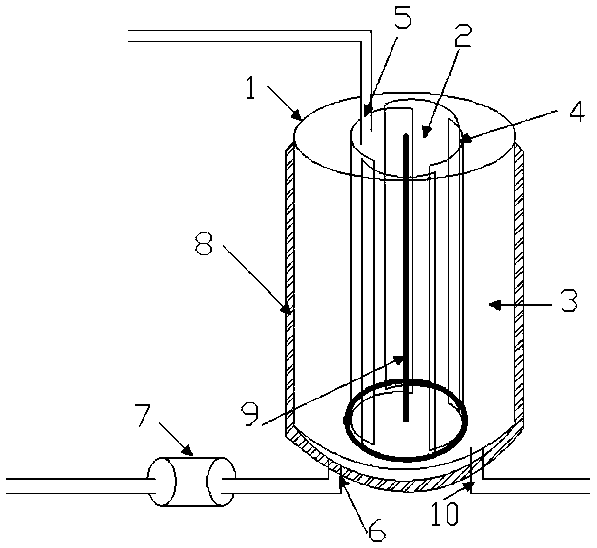
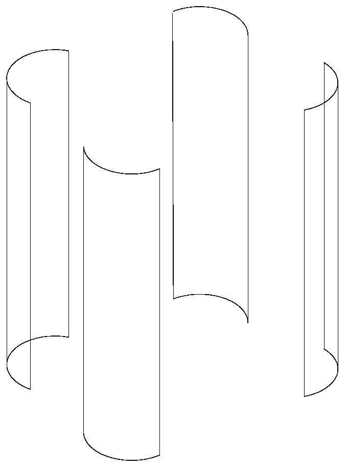
[0050] use as figure 1 The shown device comprises a reactor 1, the reactor 1 is provided with a gas feed port 5, a liquid discharge port 6 and a gas discharge port 10, the inside of the reactor 1 is provided with a light source, and is ventilated without The light-transmitting structure 4 divides the interior of the reactor 1 into at least a light-irradiated area 2 and a light-free area 3, the light-irradiated area 2 can be irradiated by light, and the light-free area 3 cannot be irradiated by light. Gas can flow between the irradiated area 2 and the light-free area 3 . The air-permeable and opaque structure described in this embodiment is a louver structure, and the schematic diagram of its components is as follows figure 2 As shown, the louver structure is composed of four curved boards. When assembled, adjacent boards are partially overlapped and gaps are left to block light and allow air to circulate. During the implementation process, the four boards can be further A r...
Embodiment 2
[0055] The device diagram of embodiment 2 is the same as that of embodiment 1, and jackets or other heat exchange equipment are respectively arranged in the light irradiation area and the no light area so as to control the temperature of the light irradiation area and the no light area respectively. Among them, a coil heat exchanger is set in the light irradiation area, and a jacket heat exchange is set outside the light-free area, and the air-permeable and opaque structure in the reactor is made of heat-insulating material. The temperature of the feed gas is 20°C, the pressure of the reactor is controlled to be 1MPa, the temperature of the light irradiation zone is controlled to be 60°C, and the average temperature of the dark zone is controlled to be 20°C. Hydrogen chloride and oxygen continuously react, and the product water and chlorine are continuously liquefied and discharged from the reactor. After being collected and further processed, liquid chlorine can be obtained. I...
Embodiment 3
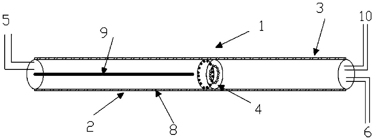
[0057] use as image 3 The shown device comprises a reactor 1, the reactor 1 is a tubular structure, the reactor 1 is provided with a gas inlet 5, a liquid outlet 6 and a gas outlet 10, a part of the reactor 1 inside A light source 9 is provided, and the other part has no light source, and the interior of the reactor 1 is divided into a light-irradiated area 2 and a light-free area 3 by a gas-permeable and opaque structure 4, the light-irradiated area 2 can be radiated by light, and The light-free zone 3 cannot be irradiated by light, and the gas between the light-irradiated zone 2 and the light-free zone 3 can communicate. The air-permeable and opaque structure described in this embodiment is a double-layer board structure, the inner and outer boards of the double-layer board are provided with staggered holes, and the outer surface of the reactor is provided with a jacket layer 8 . The light source 9 is arranged in a strip shape.
[0058] In this embodiment, a jacket layer ...
PUM
 Abstract
Description
Claims
Application Information