

Slurry for suspension plasma spraying and method for forming sprayed coating
一种等离子、悬浮液的技术,应用在金属材料涂层工艺、涂层、熔融喷镀等方向,能够解决方法产率劣化等问题,达到高抗腐蚀性的效果
- Summary
- Abstract
- Description
- Claims
- Application Information
AI Technical Summary
Problems solved by technology
Method used
Image

Examples
Embodiment 1 to 4 and comparative Embodiment 1 and 2
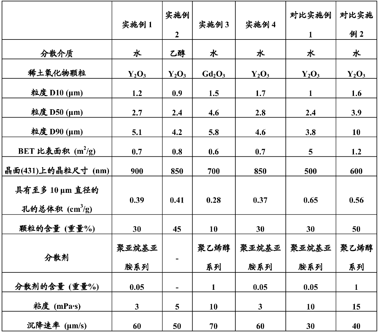
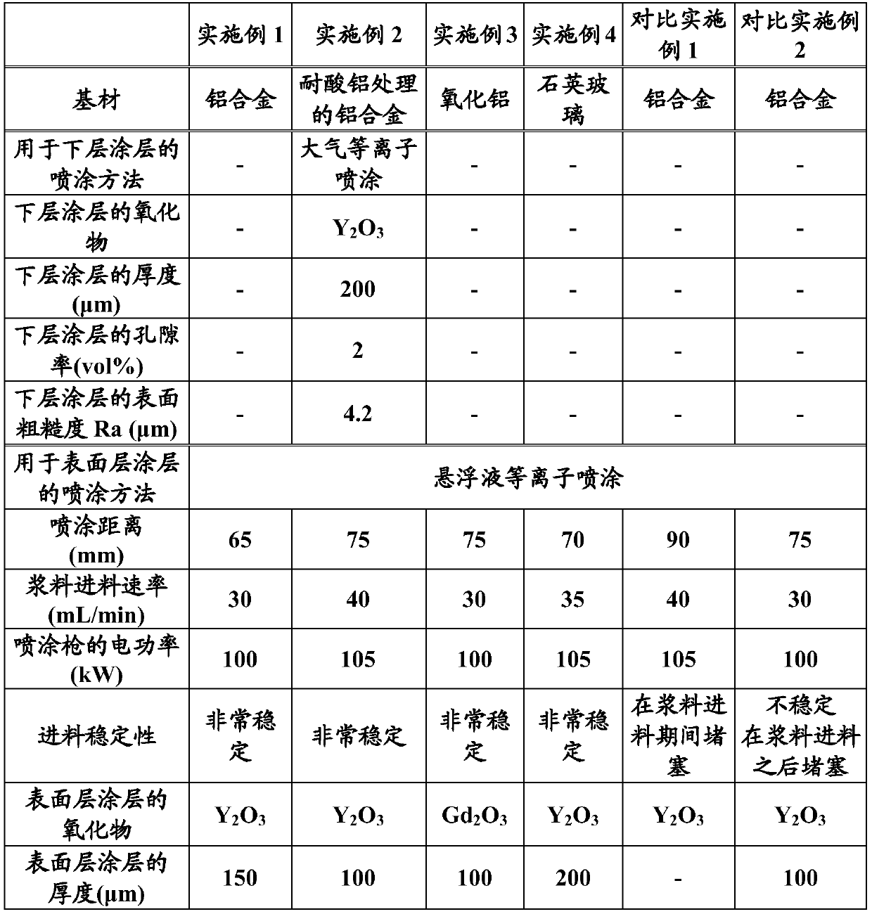
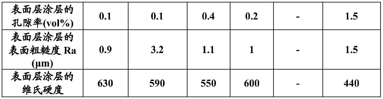
[0055] Slurries for thermal spraying shown in Table 1 including dispersion media and rare earth oxide particles were prepared. The content of the rare earth oxide particles was adjusted as shown in Table 1. The dispersants shown in Table 1 were added to the slurry in the amounts shown in Table 1, except for Example 2.
[0056] For the rare earth oxide particles, the particle sizes D10, D50, and D90, the BET specific surface area, the grain size on the crystal plane (431), and the total volume of pores having a diameter of up to 10 μm were measured by the following respective methods. In addition, for the slurry including the rare earth oxide particles, the viscosity and the sedimentation rate were measured by the following respective methods. The results are shown in Table 1.
PUM
| Property | Measurement | Unit |
|---|---|---|
| particle diameter | aaaaa | aaaaa |
| specific surface area | aaaaa | aaaaa |
| particle diameter | aaaaa | aaaaa |
Abstract
Description
Claims
Application Information