Coupling system for electric eddy current braking and regenerative braking of electric vehicle and control method thereof

An eddy current braking and eddy current braking technology, applied in electric braking systems, electric vehicles, brake transmissions, etc., can solve the problem of low braking efficiency, insufficient electromagnetic braking torque, small braking torque, etc. question

Active Publication Date: 2020-02-25
朱嘉乐
View PDF13 Cites 2 Cited by
  • Summary
  • Abstract
  • Description
  • Claims
  • Application Information

AI Technical Summary

Problems solved by technology

[0005] However, regenerative braking technology is restricted by factors such as motor characteristics and battery characteristics, and the braking torque provided is small, which cannot meet the braking needs of the car. As an auxiliary braking, it needs to be coordinated with friction braking for control
For example, when the vehicle speed decreases, the electromotive force generated by the motor is very low, and it is difficult to use DC/DC boost to charge the battery. If the motor performs pure motor energy consumption braking, the winding resistance is very small, even if the electromotive force of the generator is already small. , but the pure motor energy consumption braking current is still very large, too large will cause the motor to heat up, and it is difficult to perform regenerative braking; when braking on a long d

Method used


Image

  • Coupling system for electric eddy current braking and regenerative braking of electric vehicle and control method thereof
  • Coupling system for electric eddy current braking and regenerative braking of electric vehicle and control method thereof
  • Coupling system for electric eddy current braking and regenerative braking of electric vehicle and control method thereof

Examples


Embodiment Construction

[0063] The present invention will be further described below in conjunction with the accompanying drawings and specific embodiments, but the protection scope of the present invention is not limited thereto.

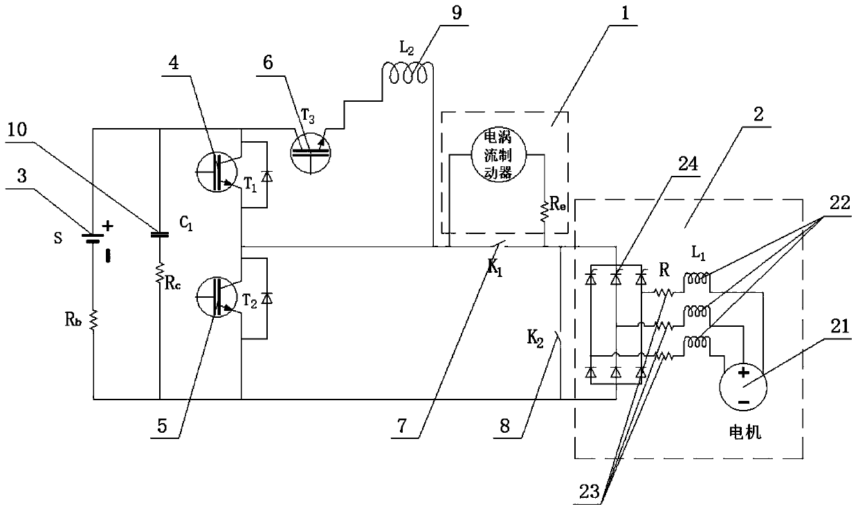
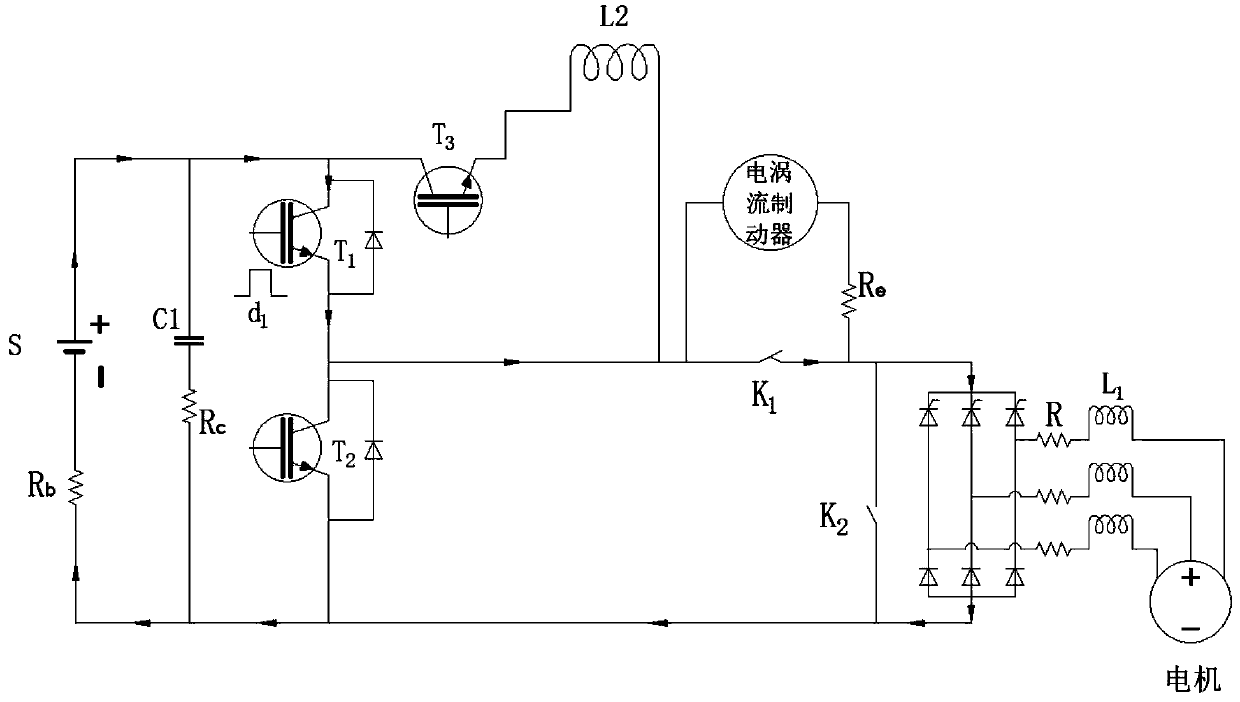
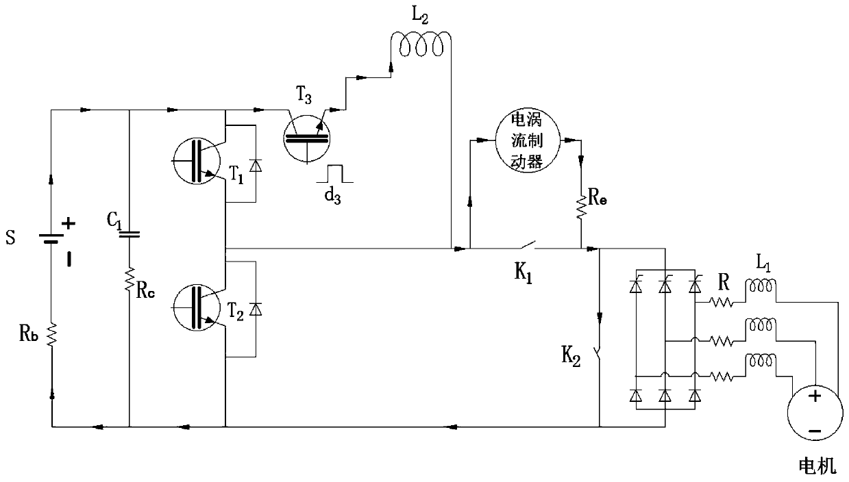
[0064] like figure 1 As shown, a coupling system of electric vehicle eddy current braking and regenerative braking includes an eddy current brake assembly 1, a motor assembly 2, an energy storage device assembly 3, an insulated gate transistor T 1 4. Insulated gate transistor T 2 5. Insulated gate transistor T 3 6. Electromagnetic relay K 1 7. Electromagnetic relay K 2 8. Inductance L 2 9 and filter capacitor C 1 Component 10; parallel with magnetic relay K 1 The eddy current brake assembly 1 of 7 is connected in parallel with the electromagnetic relay K 2 8 motor components 2 in series; the inductance L 2 9 with an insulated gate transistor T 3 6 in series with the insulated gate transistor T 1 4 in parallel, the circuit after the parallel connection is connect...


PUM


Abstract

The invention discloses a coupling system for electric eddy current braking and regenerative braking of an electric vehicle. The coupling system comprises an electric eddy current brake assembly, a motor assembly, an energy storage device assembly, an insulated gate transistor T1, an insulated gate transistor T2, an insulated gate transistor T3, an electromagnetic relay K1, an electromagnetic relay K2, an inductor L2 and a filter capacitor C1 assembly. The combined control of the insulated gate transistors and the electromagnetic relays achieves a motor driving mode, a mode of electric eddy current braking independently driven by an energy storage device, a regenerative braking mode, a regenerative braking coupling electric eddy current braking mode and a mode of electric eddy current braking independently driven by a motor. The coupling system for electric eddy current braking and regenerative braking of the electric vehicle has the beneficial effects of providing various selectable electric braking modes, improving the controllable range of electric braking torque, reducing the proportion of a friction braking system, improving the braking performance of the vehicle, enabling rectified currents to be controllable by controlling a trigger delay angle, improving the energy utilization rate, and fully recovering braking energy to a higher degree.

Description

technical field [0001] The invention relates to a braking system of an electric vehicle and a control method thereof, in particular to a coupling system of eddy current braking and regenerative braking of an electric vehicle and a control method thereof, belonging to the field of automobile braking systems. Background technique [0002] Eddy current braking is also called eddy current retarding or electromagnetic braking, and generally consists of a stator, a rotor and a fixed bracket. When the retarder is working, the stator coil is energized to generate a magnetic field, and the rotor rotates with the transmission shaft. The rotor cuts the magnetic field lines generated by the stator, thereby generating a vortex-shaped induced current inside the rotor disk. In this way, the stator will apply an electromagnetic force to the rotor that hinders the rotation of the rotor, thereby generating a braking torque. At the same time, the eddy current circulates inside the rotor disk...

Claims


Application Information

Patent Timeline
IPC IPC(8): B60L7/10B60L7/28B60T13/74
CPCB60L7/10B60L7/28B60T13/74Y02T10/72Y02T10/64
Inventor 苑磊何仁
Owner 朱嘉乐
Why Eureka
Try Eureka