
Overvoltage protection circuit and overvoltage protection method of CMOS power amplifier

An overvoltage protection circuit and overvoltage protection technology, applied in the layout of amplifier protection circuits, etc., can solve the problems of difficulty in guaranteeing work safety, CMOS power amplifiers cannot be guaranteed intact, and low reliability of power amplifiers, so as to improve safety and reliability. performance, simple and reasonable circuit design, and safe work

Pending Publication Date: 2020-02-25
ZHUHAI FUDAN INNOVATION INST
View PDF0 Cites 0 Cited by
  • Summary
  • Abstract
  • Description
  • Claims
  • Application Information

AI Technical Summary

Problems solved by technology

[0010] In view of this, the present invention provides an overvoltage protection circuit and an overvoltage protection method for a CMOS power amplifier. The circuit protects the stacked tube circuit by adding a voltage sensor voltage limiter and a subtractor on the basis of the original stacked tube circuit. The two MOS tubes in the circuit will not be broken down under extreme working conditions. Through the negative feedback regulation principle, the voltage of the entire CMOS power amplifier circuit under extreme conditions can be adjusted to a safe range, which solves the problem of high voltage in the existing CMOS power amplifier. It cannot be guaranteed that it can still be intact under extreme conditions, the reliability of the power amplifier is low, and the working safety is difficult to guarantee.

Method used


Image

  • Overvoltage protection circuit and overvoltage protection method of CMOS power amplifier
  • Overvoltage protection circuit and overvoltage protection method of CMOS power amplifier
  • Overvoltage protection circuit and overvoltage protection method of CMOS power amplifier

Examples


Embodiment Construction

[0056] The following will clearly and completely describe the technical solutions in the embodiments of the present invention with reference to the accompanying drawings in the embodiments of the present invention. Obviously, the described embodiments are only some, not all, embodiments of the present invention. Based on the embodiments of the present invention, all other embodiments obtained by persons of ordinary skill in the art without making creative efforts belong to the protection scope of the present invention.

[0057] On the one hand, see attached Figure 4 , the embodiment of the present invention discloses an overvoltage protection circuit for a CMOS power amplifier, including a stacked tube circuit, a voltage sensor U 1 , voltage limiter U 2 and the subtractor U 3 ;

[0058] One end of the stacked tube circuit is respectively connected to the voltage sensor U 1 and voltage limiter U 2 Connection, the other end of the stacked tube circuit and the subtractor U ...


PUM


Abstract

The invention discloses an overvoltage protection circuit and an overvoltage protection method of a CMOS power amplifier. The circuit comprises a stack tube circuit, a voltage sensor, a voltage amplitude limiter and a subtracter, one end of the tube stacking circuit is connected with the voltage sensor and the voltage amplitude limiter, and the other end of the tube stacking circuit is connected with the subtracter. According to the circuit, a voltage limiter and a subtracter of a voltage sensor are additionally arranged on the basis of an original stack tube circuit; the two MOS tubes in thestacked tube circuit are protected against breakdown under the limit working condition, the voltage of the whole CMOS power amplifier circuit under the limit condition can be adjusted to be within thesafety range according to the negative feedback adjustment principle, and the circuit is simple and reasonable in design, safe and reliable. Meanwhile, the method can improve the safety and reliability of the CMOS power amplifier, and guarantees that the CMOS power amplifier can still work safely under the overvoltage condition.

Description

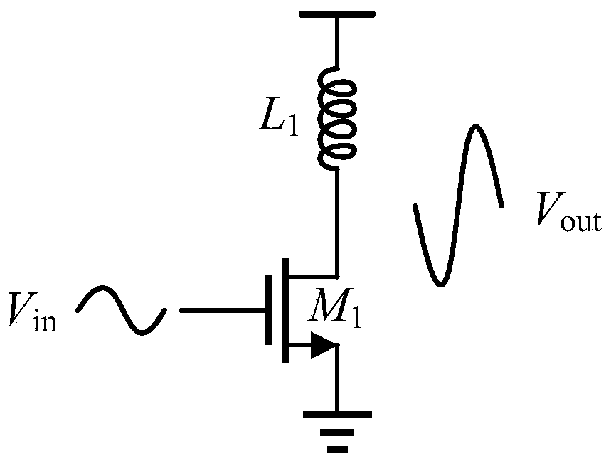
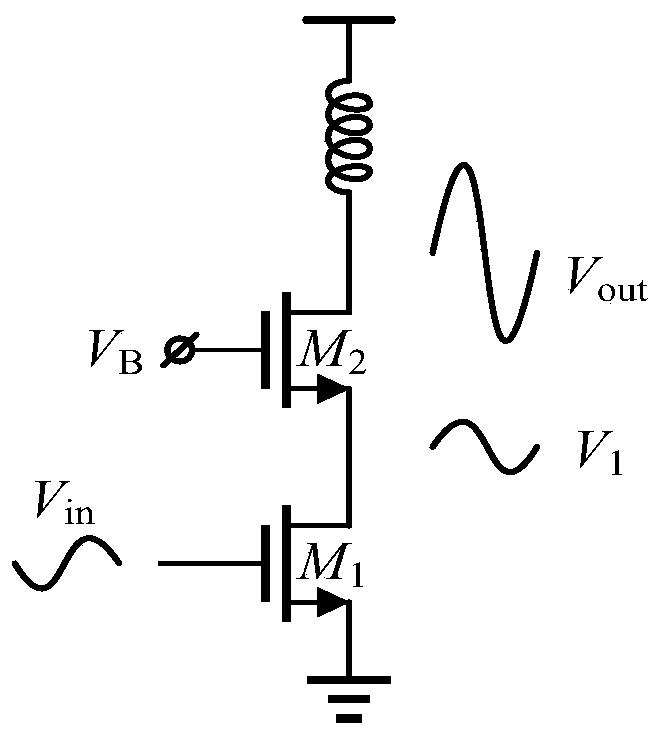
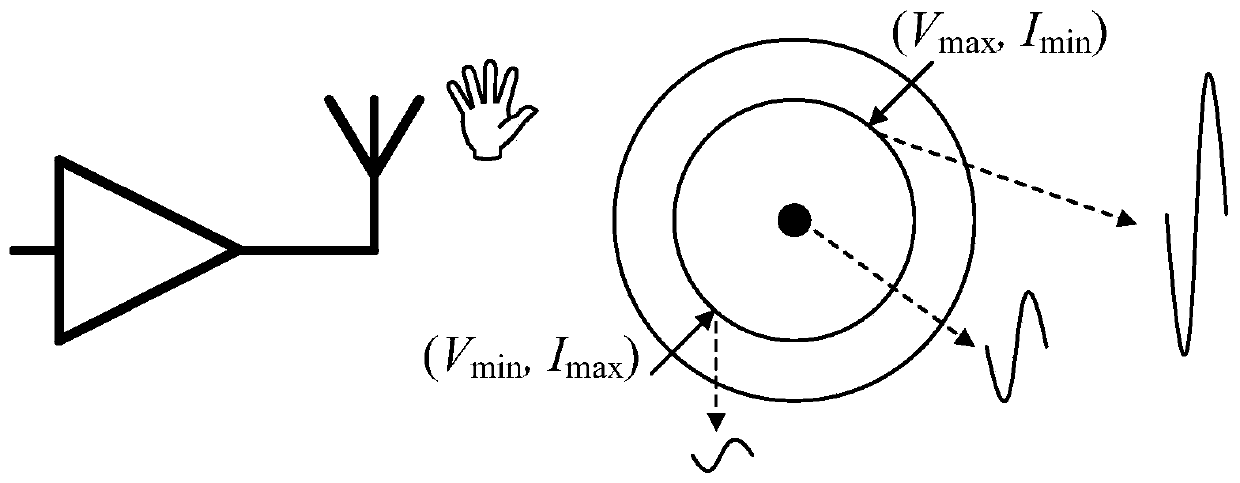
technical field [0001] The invention relates to the technical field of integrated circuit design, and more specifically relates to an overvoltage protection circuit and an overvoltage protection method of a CMOS power amplifier. Background technique [0002] At present, the CMOS process has become the mainstream process for digital circuits, analog circuits, and even radio frequency integrated circuits and millimeter wave integrated circuits due to its high integration, high yield, low cost, and devices that can further benefit from technological progress. However, in the field of power amplifiers, the CMOS process has not been well applied. The main reason is that compared with the traditional GaAs HBT (Gallium Arsenide Heterojunction Bipolar Transistor), the breakdown voltage of CMOS is relatively low. Among them, if you need to design a power amplifier, usually the structure is as follows figure 1 as shown, figure 1 Medium, M 1 is the main amplifying tube of the power ...

Claims


Application Information

Patent Timeline
IPC IPC(8): H03F1/52
CPCH03F1/52
Inventor 李露露高自立邹亮
Owner ZHUHAI FUDAN INNOVATION INST
Learn More