Method for treating drilling oil sludge mixed with oil-based drilling fluid

A lubricant, oil-based technology, applied in the field of drilling sludge treatment, can solve problems such as high operating costs, failure to achieve goals, and pollution of water sources.

Inactive Publication Date: 2020-02-28
张伟民 +2
View PDF8 Cites 2 Cited by
  • Summary
  • Abstract
  • Description
  • Claims
  • Application Information

AI Technical Summary

Problems solved by technology

[0006] 3). Pyrolysis: Its main core technology is to use a rotatable indirect heating furnace (Rotary Kiln) to indirectly heat the oil sludge at a high temperature above 550°C to evaporate the oil and water in the oil sludge, and then condense Recycling to achieve the purpose of oil, water, and solid separation; however, for oil sludge with high water content, this method directly heats the oil sludge in the furnace body, and at a high temperature of 550 ° C, water, oil, and oil-based lubrication Materials such as lubricants will produce azeotropic phenomenon and will evaporate together; after that, the recovered oil will contain a large amount of waste water, and the waste water will also contain a large amount of waste oil and oil-based lubricants. Therefore, it may be necessary to use the second or third time Distillation and separation steps, or the need to install a multi-stage reflux distillation mechanism in the distillation recovery tower is unavoidable; and because the thermal cracking method needs to adopt a low-oxygen indirect oxidation method to avoid safety problems during operation, the cracking process is also The design of batch feeding must be adopted, so the high operating cost and complicated control system are the common problems of this method
[0007] 4). Solvent extraction method: the technical core of this method is to use lipophilic extractant to add oil sludge, after sufficient homogenization, the lipophilic solvent will separate the oil from the oil sludge; this method can Most of the hydrocarbons in the solid waste in the oil sludge are freed, so that the oil content of the solid waste is lowered to less than 0.3%, which meets the requirements of high environmental protection standards; but the crux of the problem is that due to the high price of the extractant (The average unit price is 16 to 30 US dollars per liter) For the treatment of a large amount of oil sludge produced in thousands of kilograms (1000kg) or MT during drilling, this is a method that is difficult to be applied commercially
[0008] However, as mentioned above, due to the complex composition of drilling mud, it not only contains crude oil, kaolin, illite, mud, sandstone, barite powder, oil-based lubricants, and some even contain xanthan gum. Therefore, the oil sludge discharged from drilling The composition is complex and the structure is solid, and the hydrocarbons, including paraffin and asphaltene, deeply hidden in solid waste cannot be completely removed by hydrocyclone or cascade three-phase separation device
Therefore, although the solid / liquid separation step has been done, the oil content in the solid waste is still as high as 2-3%, and some even reach as high as 5-6%. The hydrocarbons in it may form leakage and cause soil pollution. If the total amount of leakage increases, it may further pollute water sources or cause safety incidents, and even cause air pollution.
[0009] Therefore, if the decree requires the industry to do ultimate disposal of these remaining solid wastes, at present, the choice of the industry is to dispose of them only by "incineration method", which will not only cause air pollution problems, but also waste useful resources
Therefore, at this moment when environmental protection issues are becoming more and more serious, at present, the above two simple methods or steps to treat drilling mud will inevitably fail to achieve the goal

Method used


Image

  • Method for treating drilling oil sludge mixed with oil-based drilling fluid
  • Method for treating drilling oil sludge mixed with oil-based drilling fluid
  • Method for treating drilling oil sludge mixed with oil-based drilling fluid

Examples


Embodiment Construction

[0095] The technical solutions in the embodiments of the present invention are clearly and completely described below in conjunction with the drawings in the embodiments of the present invention. In the following description, a lot of specific details are set forth in order to fully understand the present invention, but the present invention can also be implemented in other ways different from those described here, and those skilled in the art can do it without departing from the meaning of the present invention. By analogy, the present invention is therefore not limited to the specific examples disclosed below.

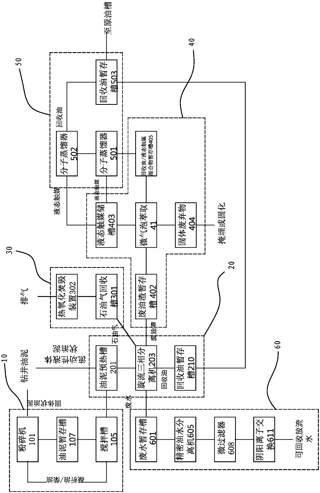
[0096] see figure 1 , the method for the present invention to process the drilling sludge mixed with oil-based lubricants comprises a selectively used sludge homogenization step 10, a cyclone three-phase separation step 20, a petroleum gas oxidation incineration step 30, a solid waste Extraction step 40, a liquid catalyst recovery step 50, and application of related...


PUM

PropertyMeasurementUnit
particle diameteraaaaaaaaaa
thicknessaaaaaaaaaa

Abstract

The invention relates to a method for treating drilling oil sludge mixed with an oil-based drilling fluid, wherein the method comprises a selectively-used sludge homogenizing step, a rotational flow three-phase separation step, a petroleum gas oxidation incineration step, a liquid-state catalyst extraction step and a liquid-state catalyst recovery step. According to the method, the oil product generated in the rotational flow three-phase separation step is recovered to a recovered oil temporary storage tank so as to be conveniently conveyed to a crude oil tank to be sold, and the waste gas isintroduced into the petroleum gas oxidation incineration step so as to be subjected to oxidation incineration; and the solid waste generated in the liquid-state catalyst extraction step can be directly buried or can be utilized after being solidified, the crude oil and liquid-state catalyst mixture produced in the liquid-state catalyst extraction step is firstly fed into a mixed liquid temporary storage tank, and the liquid-state catalyst is recycled after being fed in the later liquid-state catalyst recovery step.

Description

technical field [0001] The invention relates to a method for processing drilling oil mud, in particular to a method for processing drilling oil mud mixed with oil-based lubricant. Background technique [0002] Deep wells drilled for the type of hydrocarbons produced are usually classified as "Oil Well" or Gas Well; and during the drilling process, in order to keep the drill bit and the surface lubricated and avoid drill bit wear Too fast, most of the lubricants will be sprayed on the drill bit (Drilling fluid), and the most widely used lubricants are oil-based lubricants (Oil Base Drilling Fluid such as Shell Saralin V815); It is an ancient formation, therefore, it also contains a large amount of minerals such as kaolin, illite, montmorillonite, and chlorite; in addition, because the drilling operation must try to avoid the collapse of the well wall, so the operation will also Barite powder (Barite) and even xanthan gum (Xanthan Gum) and other additives are added during the...

Claims


Application Information

Patent Timeline
Patent Type & Authority Applications(China)
IPC IPC(8): C02F11/00C02F11/13C02F11/127C02F9/04F23G7/06C10G1/00
CPCC02F11/00C02F11/127C02F9/00F23G7/06C10G1/006C02F2301/08C02F1/40C02F1/001C02F1/42
Inventor 张伟民张正颖张睿庭
Owner 张伟民
Why Eureka
Try Eureka