Glass corrosion composite mask structure and glass corrosion method

A composite mask and glass technology, applied in the field of microelectronics, can solve the problems of high cost, weak bonding force between glass and silicon wafer, large lateral corrosion of glass, etc., and achieve the effect of convenient setting.

Pending Publication Date: 2020-02-28
INST OF ELECTRONICS ENG CHINA ACAD OF ENG PHYSICS
View PDF1 Cites 4 Cited by
  • Summary
  • Abstract
  • Description
  • Claims
  • Application Information

AI Technical Summary

Problems solved by technology

In addition, literature reports use polysilicon, amorphous silicon or single crystal silicon as a mask, and the glass corrosion depth is relatively large.
For example, using LPCVD to deposit polysilicon as a mask, when the thickness of the mask is 500nm, a glass etching depth greater than 400μm can be obtained. Mask can obtain a glass etching depth greater than 500 μm. Before glass etching, this method needs to use anodic bonding to bond single crystal silicon and glass together, and then use plasma etching or KOH solution etching to thin the silicon wafer. The method is expensive and time-consuming, and the bond has a large thermal stress
Zhang Zhaoyun, Institute of Electronic Engineering, China Academy of Engineering Physics and others proposed a method of using hydroxide catalytic bonding to bond glass and silicon wafers, using single crystal silicon as a mask to corrode glass (application number: 201710206914.7). Although the method can avoid the thermal stress caused by the anodic bonding temperature and is easy to operate, the bonding force between the glass and the silicon wafer is weak, and it is easy to detach, and the glass has a large lateral corrosion

Method used


Image

  • Glass corrosion composite mask structure and glass corrosion method
  • Glass corrosion composite mask structure and glass corrosion method
  • Glass corrosion composite mask structure and glass corrosion method

Examples


Embodiment 1

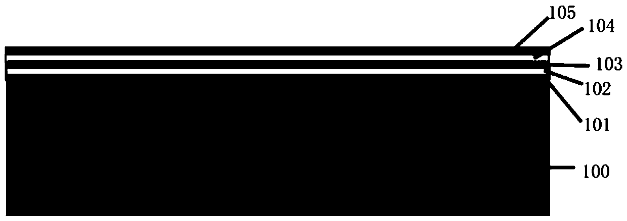
[0037] Such as figure 1 As shown, according to an embodiment of the present invention, a composite mask structure for glass corrosion is provided, including: a first metal primer layer 101, a first metal layer 102, and a second metal primer layer 103 arranged sequentially from a glass substrate 100 , the second metal layer 104 and the photoresist layer 105;

[0038] Wherein, the first metal primer layer 101 and the second metal primer layer 103 are metal Cr layers with a thickness of 10-50nm;

[0039] Wherein, the first metal layer 102 and the second metal layer 104 are metal Au or metal Cu with a thickness of 100-500 nm;

[0040] Wherein, the photoresist layer 105 is made of SU-8 2025 photoresist with a thickness of 1-50 μm.

[0041] Specifically, through the setting of the first metal primer layer 101, the first metal layer 102, the second metal primer layer 103, and the second metal layer 104, the combination with the glass substrate 100 is good, and the glass corrosion d...

Embodiment 2

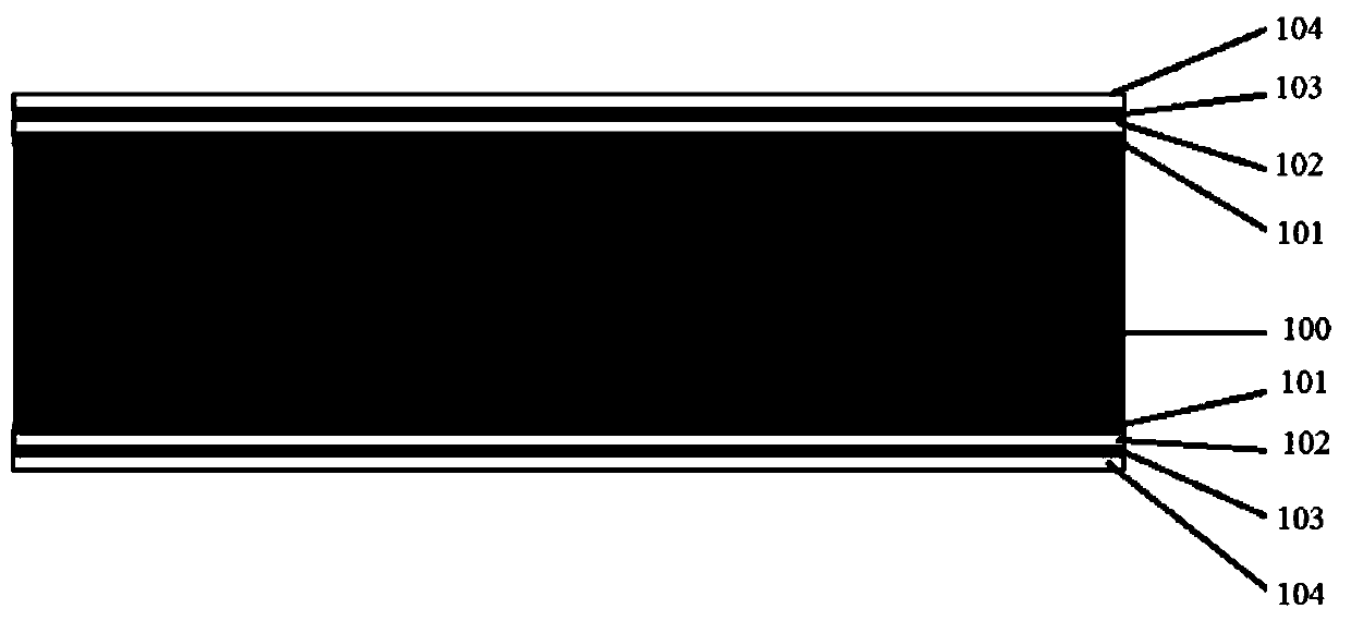
[0043] Figure 2a-Figure 2g A schematic diagram showing a glass etching method according to another embodiment of the present invention. In this embodiment, the glass substrate 100 is 7740 glass with a thickness of 1000 μm. According to another embodiment of the present invention, a method for glass corrosion is provided, including:

[0044] (a) Clean the glass substrate 100 with a mixed liquid of sulfuric acid and hydrogen peroxide, and sputter the first metal primer layer 101 (chrome Cr), the first metal layer 102 (gold Au), and the second metal primer layer on the upper and lower sides of the glass substrate 100 sequentially. The bottom layer 103 (chromium Cr), the second metal layer 104 (gold Au), the thickness is respectively Such as Figure 2a shown;

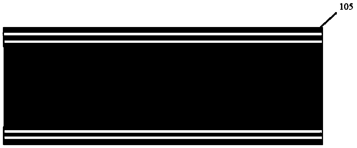
[0045] (b) Spin-coat SU-8 2025 photoresist on the upper and lower sides of the substrate with a thickness of 30 μm, such as Figure 2b shown;

[0046] (c) Photolithography on one side of the substrate to form the ...


PUM

PropertyMeasurementUnit
thicknessaaaaaaaaaa
thicknessaaaaaaaaaa
thicknessaaaaaaaaaa

Abstract

The invention provides a glass corrosion composite mask structure and a glass corrosion method. The glass corrosion composite mask structure comprises a first metal priming coat layer, a first metal layer, a second metal priming coat layer, a second metal layer and a photoresist layer which are sequentially arranged from a glass substrate, wherein the first metal priming coat layer and the secondmetal priming coat layer are metal Cr layers; the first metal layer and the second metal layer are made of metal Au or metal Cu. According to the composite mask structure for glass corrosion, the glass corrosion depth can be increased, the bonding performance of masks and glass is good, and meanwhile the complex stress control problem of polycrystalline silicon and monocrystalline silicon can be avoided.

Description

technical field [0001] The invention belongs to the technical field of microelectronics, and more specifically relates to a composite mask structure for glass corrosion and a method for glass corrosion. Background technique [0002] Glass has a wide range of uses, and the masks used for etching include photoresist, Cr / Au, Ti / Au, silicon carbide, etc., but using these materials as masks, the etching depth of glass is small, generally less than 50 μm. In addition, it is reported in the literature that using polysilicon, amorphous silicon or single crystal silicon as a mask, the etching depth of glass is relatively large. For example, using LPCVD to deposit polysilicon as a mask, when the thickness of the mask is 500nm, a glass etching depth greater than 400μm can be obtained. Mask can obtain a glass etching depth greater than 500 μm. Before glass etching, this method needs to use anodic bonding to bond single crystal silicon and glass together, and then use plasma etching or ...

Claims


Application Information

Patent Timeline
Patent Type & Authority Applications(China)
IPC IPC(8): C03C15/00C03C17/38
CPCC03C15/00C03C17/38
Inventor 张照云唐彬刘显学熊壮李枚许蔚苏伟彭勃
Owner INST OF ELECTRONICS ENG CHINA ACAD OF ENG PHYSICS
Why Eureka
Try Eureka