
Voltage stabilizing device and method for stabilizing voltage jump of DC bus based on super capacitors

A technology of DC bus voltage and super capacitor, applied in the field of DC power grid, can solve the problems of reducing the operating efficiency and life of data center equipment, threats to the safety of data center equipment, and switching power supply out of operation, so as to improve the quality of power supply and stabilize the DC bus voltage. The effect of fluctuating and smoothing the sudden change of DC bus voltage

Active Publication Date: 2020-02-28
STATE GRID CORP OF CHINA +1
View PDF5 Cites 5 Cited by
  • Summary
  • Abstract
  • Description
  • Claims
  • Application Information

AI Technical Summary

Problems solved by technology

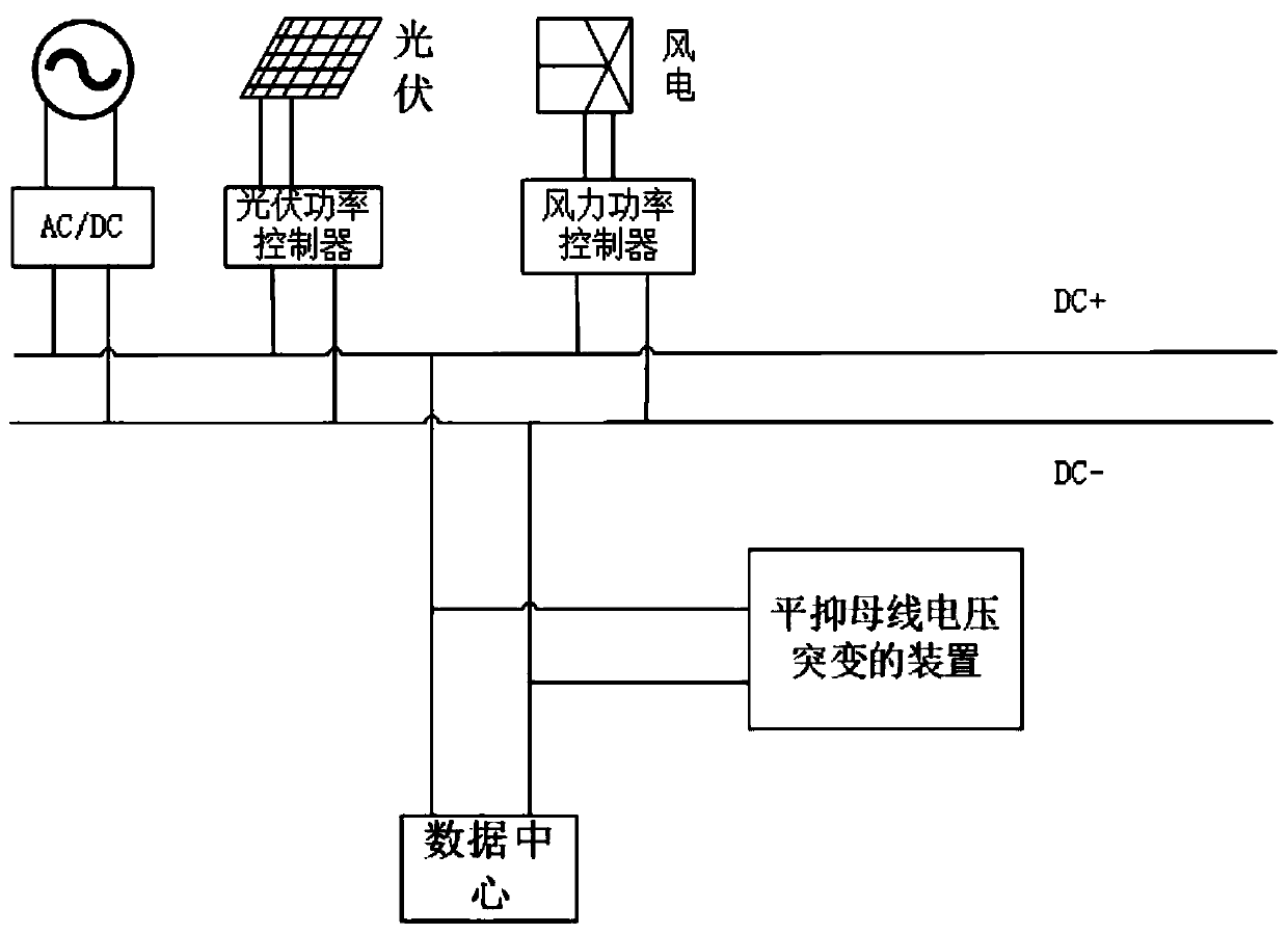
[0003] The data center is one of the typical loads in the smart park. When the bus voltage changes suddenly, it will pose a great threat to the safety of the data center equipment.
It may cause system oscillation, over-voltage or under-voltage protection malfunction, which may reduce the operating efficiency and life of the equipment in the data center, or cause a large number of switching power supplies used in the data center to stop running, and even burn the equipment in severe cases
[0004] In the existing technology, busbar voltage fluctuations can only be stabilized in the AC system. With the development of the DC distribution network, a bus voltage stabilization device for the DC distribution network is needed when the voltage of the DC distribution network suddenly changes. , to ensure the stable operation of the load

Method used


Image

  • Voltage stabilizing device and method for stabilizing voltage jump of DC bus based on super capacitors
  • Voltage stabilizing device and method for stabilizing voltage jump of DC bus based on super capacitors
  • Voltage stabilizing device and method for stabilizing voltage jump of DC bus based on super capacitors

Examples


Embodiment Construction

[0033] The present invention is described in further detail below:

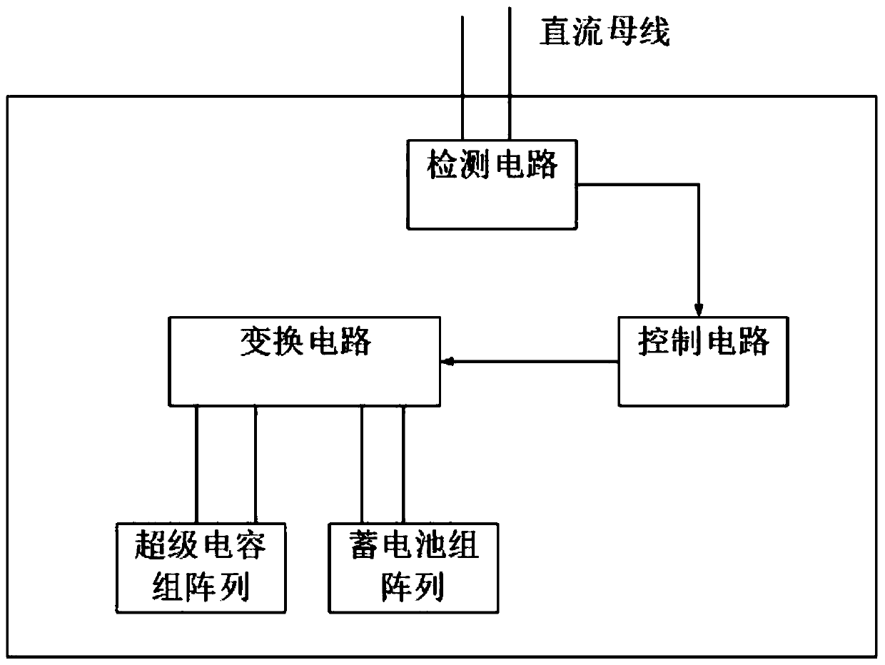
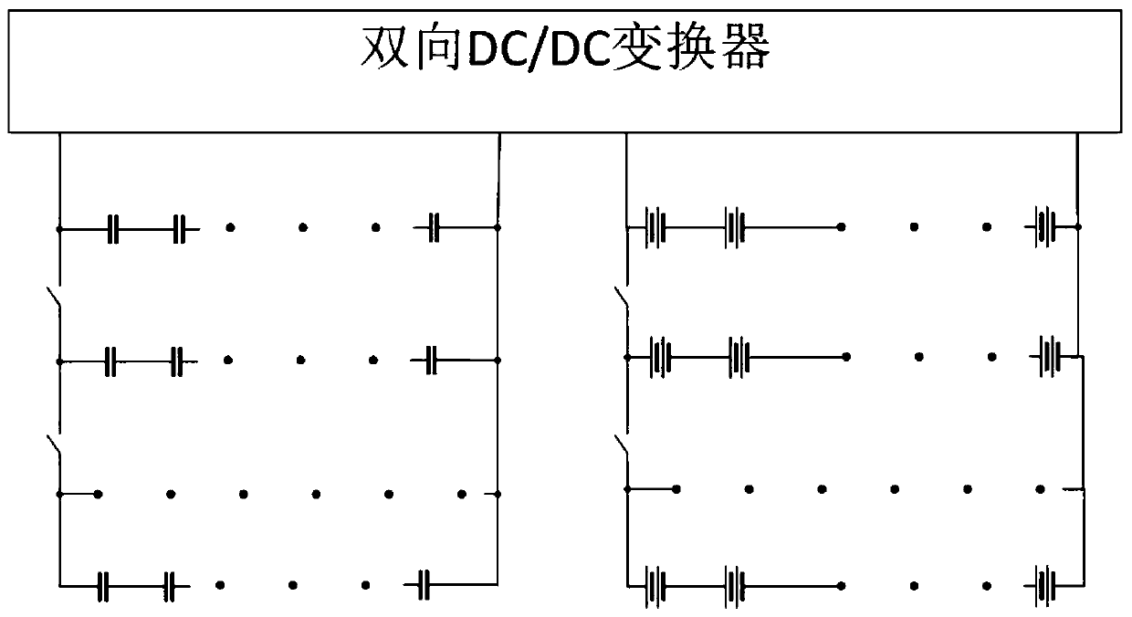
[0034]A voltage stabilization device based on a supercapacitor to stabilize a sudden change in DC bus voltage, including a detection circuit, a control circuit, a conversion circuit, and a hybrid energy storage module, wherein the detection circuit is connected in parallel to the DC bus through a voltage sensor; the control circuit is based on the detected DC The voltage value on the bus controls the on-off of the voltage compensation bus circuit and the capacitor charging circuit. Wherein the control circuit includes a central processing unit, and also includes peripheral circuits that assist the central processing unit, and the central processing unit controls the on-off of the conversion circuit according to the detected voltage value on the DC bus; the conversion circuit adopts a bidirectional DC-DC conversion The inverter can not only realize the charging of the hybrid energy storage module but also enab...


PUM


Abstract

The invention discloses a voltage stabilizing device and method for stabilizing voltage jump of a DC bus based on super capacitors. The voltage stabilizing device comprises a detection circuit, a control circuit, a conversion circuit, and a hybrid energy storage module. The detection circuit is connected to a DC bus through a voltage sensor and a current sensor. The control circuit comprises a central processing unit, and the central processing unit controls the on-off of a voltage compensation bus loop and a capacitor charging loop according to a detected voltage value on the DC bus. The conversion circuit adopts a bidirectional DC / DC Buck-Boost circuit and is used for charging the hybrid energy storage module or enabling the hybrid energy storage module to compensate a DC power grid. Thehybrid energy storage module comprises a super capacitor bank array and a storage battery pack array. The super capacitor bank array is composed of a plurality of unit super capacitors in a series-parallel connection mode, and the storage battery pack array is composed of a plurality of unit storage batteries in a series-parallel connection mode. The electric energy quality of a data center in anintelligent park can be improved, and the stability of the incoming line voltage of the data center can be ensured.

Description

technical field [0001] The invention belongs to the technical field of direct current power grids, and in particular relates to a voltage stabilizing device and a method for stabilizing a sudden change in the voltage of a direct current bus based on a supercapacitor. Background technique [0002] With the development of distributed power supply, DC microgrid is widely used as an efficient utilization system. A DC microgrid is generally composed of power modules such as multiple power supplies and constant power loads. When a distributed power supply or load is switched into a DC grid, it will cause a sudden change in the bus voltage, and because the distributed energy in the microgrid is easily affected by environmental factors , leading to the fluctuation and randomness of the output power, which further leads to sudden changes in voltage. There are two specific forms of voltage mutation: one is voltage drop, and the other is voltage overshoot. [0003] The data center is...

Claims


Application Information

Patent Timeline
IPC IPC(8): H02J7/34H02J1/10
CPCH02J1/10H02J7/34H02J7/345
Inventor 蒋琪蒋勃郝伟赵蕾杨旭张欣宜薛倩楠王刚高传彬李建兴陈延枫杨智高家辉薛军贺军荪靳媛彭芳薛晶陈晓贾静寇磊李尧张睿喆韩波
Owner STATE GRID CORP OF CHINA
Learn More