Low-profile wide-angle scanning all-metal multi-beam lens antenna

A technology of wide-angle scanning and lens antennas, which is applied in leaky waveguide antennas, antennas, antenna arrays, etc., can solve the problems of increased strength, high antenna overall section, difficult engineering and practical application of antennas, etc., and achieves miniaturized structure and good focusing performance , the effect of simplifying the section height

Active Publication Date: 2020-03-17
UNIV OF ELECTRONICS SCI & TECH OF CHINA
View PDF7 Cites 11 Cited by
  • Summary
  • Abstract
  • Description
  • Claims
  • Application Information

AI Technical Summary

Problems solved by technology

The antenna uses a uniform dielectric cylinder as the lens, and its antenna aperture efficiency is low, which cannot be compared with the layered equivalent Lunberg cylindrical lens; It is not compact enough, and at the same time, the antenna does not add any metal reinforcement between the parallel plates to effectively increase the strength, so that the antenna is stable whether it is the dielectric lens in a single layer, the stability of the feed, or the stability between layers The problems have not been solved, and the antenna is difficult to be practical in engineering
In 2013, Hua Changzhou and others published a paper entitled "Air-filled parallel-plate cylindrical modified Luneburg lens antenna formultiple-beam In the paper "scanning at millimeter-wave frequencies", a parallel-plate cylindrical Lunberg lens antenna completely filled with air is designed. Although the antenna can realize 160° wide-angle beam scanning in the azimuth plane, the antenna works in TE mode, and the antenna height Must be greater than half a wavelength, making the overall profile of the antenna higher

Method used


Image

  • Low-profile wide-angle scanning all-metal multi-beam lens antenna
  • Low-profile wide-angle scanning all-metal multi-beam lens antenna
  • Low-profile wide-angle scanning all-metal multi-beam lens antenna

Examples


Embodiment Construction

[0015] specific implementation plan

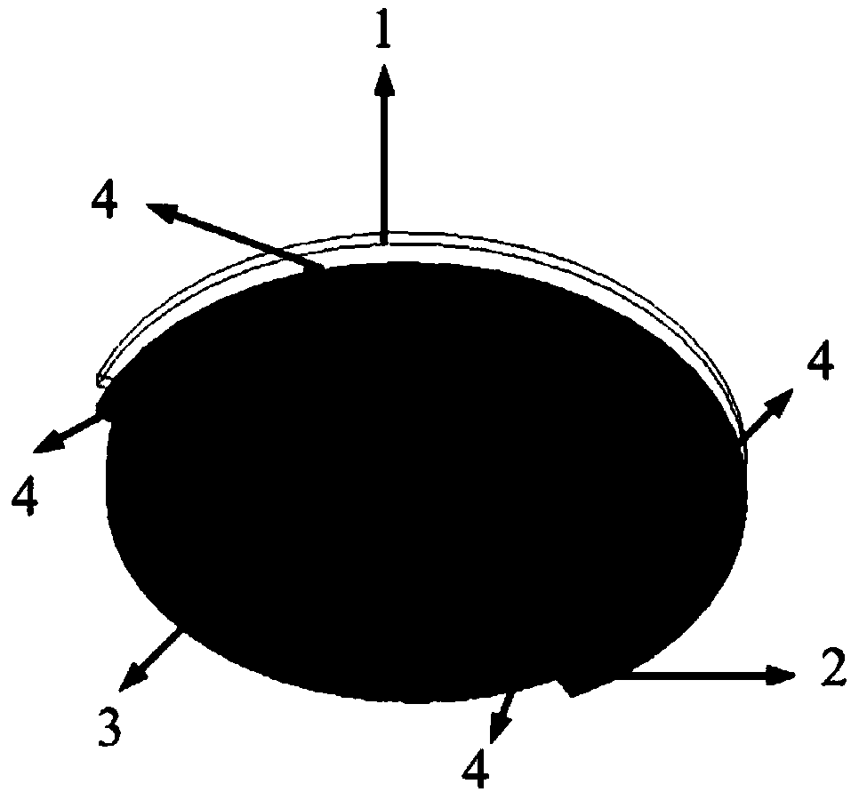
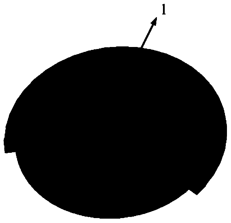
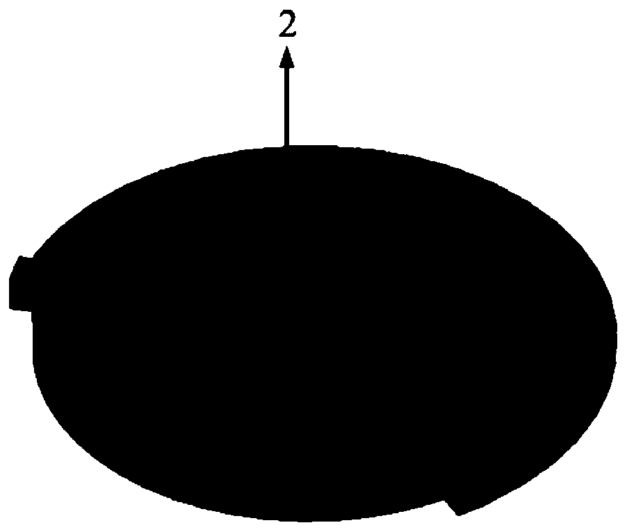
[0016] figure 1 , figure 2 , image 3 and Figure 4 The design structure diagram of the all-metal multi-beam lens antenna with low profile and wide-angle scanning is described in detail. According to the illustration, this device mainly includes the upper layer 1 of the metal parallel plate, the lower layer 2 of the metal parallel plate, and the arc array 3 composed of 18 microstrip feed antennas in the all-metal lens antenna, which are used to fix the upper layer 1 and the lower layer of the metal parallel plate. The metal screw 4 of the lower layer 2 of the metal parallel plate. The maximum aperture size of the lens antenna is 122×5mm 2 , the focal length of the feed source from the lens is 5mm, and the distance between the metal parallel upper layer 1 and the metal parallel plate lower layer 2 is selected as 1.5mm, which is much smaller than the wavelength at the design center frequency of 28GHz. Common lens antenna feeds are mai...


PUM


Abstract

The invention discloses a low-profile wide-angle scanning all-metal multi-beam lens antenna which realizes the 126-degree beam scanning of an azimuth plane and a wide beam of which the pitch plane isgreater than 60 degrees. The basic structure of the antenna comprises a metal parallel plate upper layer, a metal parallel plate lower layer, an arc-shaped array composed of 18 microstrip feed sourceantennas, and metal screws used for fixing the metal parallel plate upper layer and the metal parallel plate lower layer, wherein the metal parallel plate upper layer is slotted, the ridge adding processing is carried out on the corresponding position of the metal parallel plate lower layer, and a metal fixing structure is added to a feed source array, so that the overall strength is improved. According to the lens antenna designed by the scheme, the single-mode transmission of a TEM mode between the parallel plate waveguides is realized, and the profile height can be limited to be less than or equal to half wavelength, so that the antenna has the advantages of low profile, low manufacturing cost, small size, easiness in integration and convenience in engineering realization, and is particularly suitable for the millimeter wave frequency bands and the application scenes needing axial array formation.

Description

technical field [0001] The invention relates to a lens antenna belonging to the technical field of antenna engineering, in particular to an all-metal multi-beam lens antenna with a low profile and wide-angle scanning for multi-beam directional communication, especially suitable for working in vehicles, airborne , shipboard, base station and small station and other application scenarios, and the antenna cost is low, small in size, easy to integrate and high in structural strength. Background technique [0002] With the increasing demand for multi-beam communication antennas in technical fields such as satellite communication, electronic countermeasures, and target tracking, correspondingly, the electrical performance requirements of multi-beam communication antennas are also getting higher and higher. , low sidelobe, wide beam coverage and other requirements, it is also necessary to take into account the requirements of cost, application environment universality, etc., especi...

Claims


Application Information

Patent Timeline
Patent Type & Authority Applications(China)
IPC IPC(8): H01Q1/38H01Q13/20H01Q19/06H01Q21/00
CPCH01Q1/38H01Q13/206H01Q19/06H01Q21/00
Inventor 杨仕文刘坤宁黄明屈世伟陈益凯胡俊
Owner UNIV OF ELECTRONICS SCI & TECH OF CHINA
Why Eureka
Try Eureka