Double-optical-comb multi-frequency-multiplication-factor frequency spectrum spread frequency modulation signal generation system and implementation method thereof

A technology of spectrum spread and FM signal, which is applied in the field of spectrum spread FM signal generation system, can solve the problems of restricting the detection accuracy and resolution ability of the radar system, the deterioration of signal quality, and the complex structure of the system, so as to achieve wide application prospects, improve the detection distance and Resolution, Extended Range Effects

Active Publication Date: 2020-03-17
NORTHWESTERN POLYTECHNICAL UNIV
View PDF8 Cites 9 Cited by
  • Summary
  • Abstract
  • Description
  • Claims
  • Application Information

AI Technical Summary

Problems solved by technology

The traditional chirp signal generation method based on direct digital synthesis (DDS) is limited by the frequency dependence of electronic devices. To generate high-frequency, large-bandwidth chirp signals (generally frequency <10GHz, bandwidth <2GHz), it often requires multiple mixing Frequency and filtering, resulting in complex system structure, deterioration of signal quality, and the disadvantages of high cost, poor reconfigurability, low power efficiency and large size and weight, which seriously restrict the detection accuracy and resolution ability of the radar system

Method used


Image

  • Double-optical-comb multi-frequency-multiplication-factor frequency spectrum spread frequency modulation signal generation system and implementation method thereof
  • Double-optical-comb multi-frequency-multiplication-factor frequency spectrum spread frequency modulation signal generation system and implementation method thereof
  • Double-optical-comb multi-frequency-multiplication-factor frequency spectrum spread frequency modulation signal generation system and implementation method thereof

Examples


Embodiment

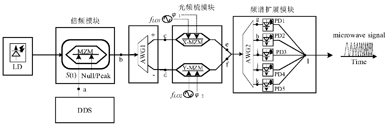
[0065] Through the optical system simulation software, the spectrum splicing scheme based on double frequency and five-wire dual optical comb is simulated and analyzed. The simulation schematic diagram is as follows figure 1 Shown:

[0066] The devices needed in the simulation include: chirp source, continuous laser, MZM, optical combiner, wavelength division multiplexer (WDM), optical amplifier (EDFA) and PD and other devices. The main simulation parameters of the system are configured as follows:

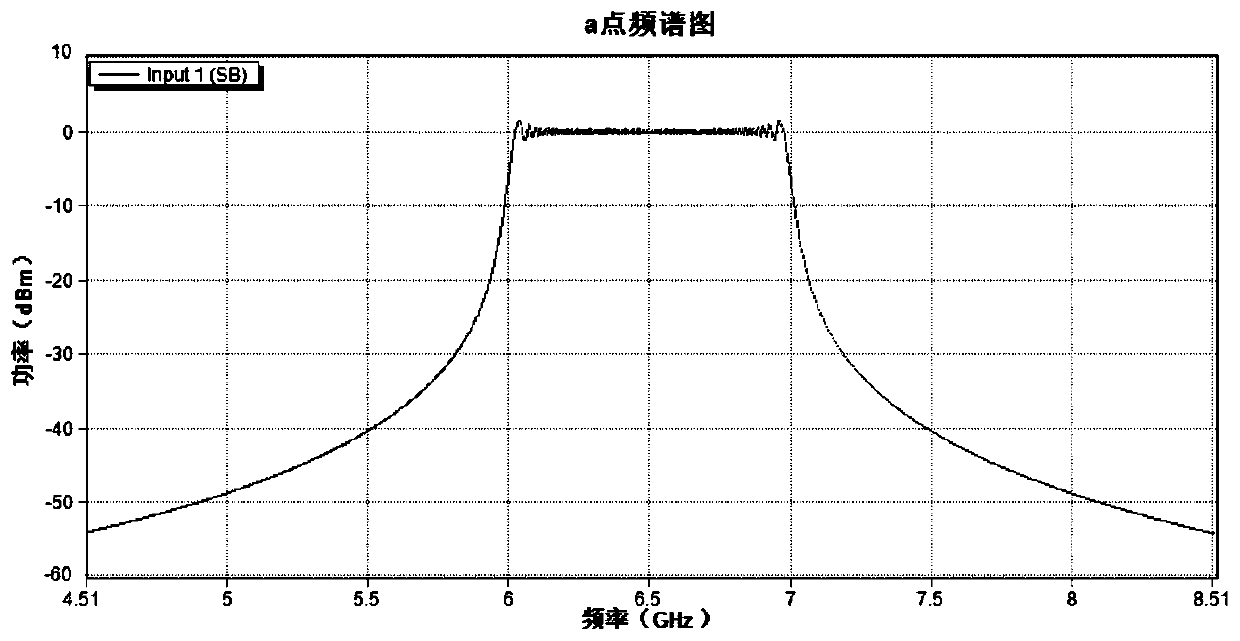
[0067] Broadband IF chirp signal: center frequency 6.5GHz, bandwidth 1GHz;

[0068] Laser: output power 40mw, relative intensity noise (RIN) -155dB / Hz, line width 100kHz, wavelength 1552nm;

[0069] Modulator: half-wave voltage 5V, insertion loss 5dB, extinction ratio 35dB;

[0070] EDFA: APC mode, output power 100mW, noise figure 5;

[0071] PD: Responsivity 0.7W / A.

[0072] Steps:

[0073] Step 1: Configure the chirp signal generation unit to generate the original chirp si...


PUM

PropertyMeasurementUnit
frequencyaaaaaaaaaa

Abstract

The invention provides a double-optical-comb multi-frequency-multiplication-factor frequency spectrum spread frequency modulation signal generation system and an implementation method thereof. A laserand a direct digital synthesizer provide optical carriers and linear frequency modulation signals for a frequency multiplication module. The frequency multiplication module realizes photoelectric conversion and frequency multiplication of electric signals, the optical frequency comb module generates five-line optical frequency combs. Five paths of optical signals are respectively injected into the five PDs connected in parallel for photoelectric detection, the obtained electric signals are subjected to frequency spectrum splicing, and 10/20 frequency multiplication linear frequency modulationsignal frequency spectrum expansion can be realized. According to the invention, the generation of high-frequency and large-bandwidth linear frequency modulation signals is effectively realized, andthe method has the characteristics of simple structure, frequency agility and small channel interference. Microwave photonics technology is adopted to fuse the multi-frequency multiplication technology and the optical frequency comb technology so that the range of the carrier frequency and the bandwidth of an original linear frequency modulation signal is expanded, and the requirements for the frequency and the bandwidth of the linear frequency modulation signal are remarkably reduced.

Description

technical field [0001] The invention relates to the field of radar detection, in particular to a spectrum spread FM signal generation system and a realization method. Background technique [0002] The chirp signal has the advantages of large instantaneous bandwidth, high distance resolution and high detection characteristics of moving targets, and is widely used in pulse compression radar and electronic warfare systems. Using a long-lasting broadband chirp signal can transmit more energy with a smaller peak power, avoiding the problem of power saturation in the transmitter in pulse radar, and reducing the requirements for system complexity. Therefore, the use of broadband chirp signals can achieve longer detection range, higher spatial resolution, and lower probability of interception and interference. The traditional chirp signal generation method based on direct digital synthesis (DDS) is limited by the frequency dependence of electronic devices. To generate high-frequenc...

Claims


Application Information

Patent Timeline
Patent Type & Authority Applications(China)
IPC IPC(8): H04B1/707H04B10/516H04B10/548
CPCH04B1/707H04B10/548H04B10/5165
Inventor 高永胜王武营王鑫圆谭庆贵高许岗樊养余齐敏
Owner NORTHWESTERN POLYTECHNICAL UNIV
Why Eureka
Try Eureka