Equipment for reproductive system

A technology of reproductive system and equipment, which is applied in the direction of massage, application of genitalia, instruments of medicine, etc.

Pending Publication Date: 2020-03-24
李辉
View PDF0 Cites 0 Cited by
  • Summary
  • Abstract
  • Description
  • Claims
  • Application Information

AI Technical Summary

Problems solved by technology

[0004] Because the ovary is located in the deep part of the human body, it is difficult to massage it with an ordinary massager, so there is no massage equipment for the ovary on the market

Method used


Image

  • Equipment for reproductive system
  • Equipment for reproductive system
  • Equipment for reproductive system

Examples


Embodiment 1

[0086] Embodiment 1 is an embodiment of the device for treating female infertility of the present invention.

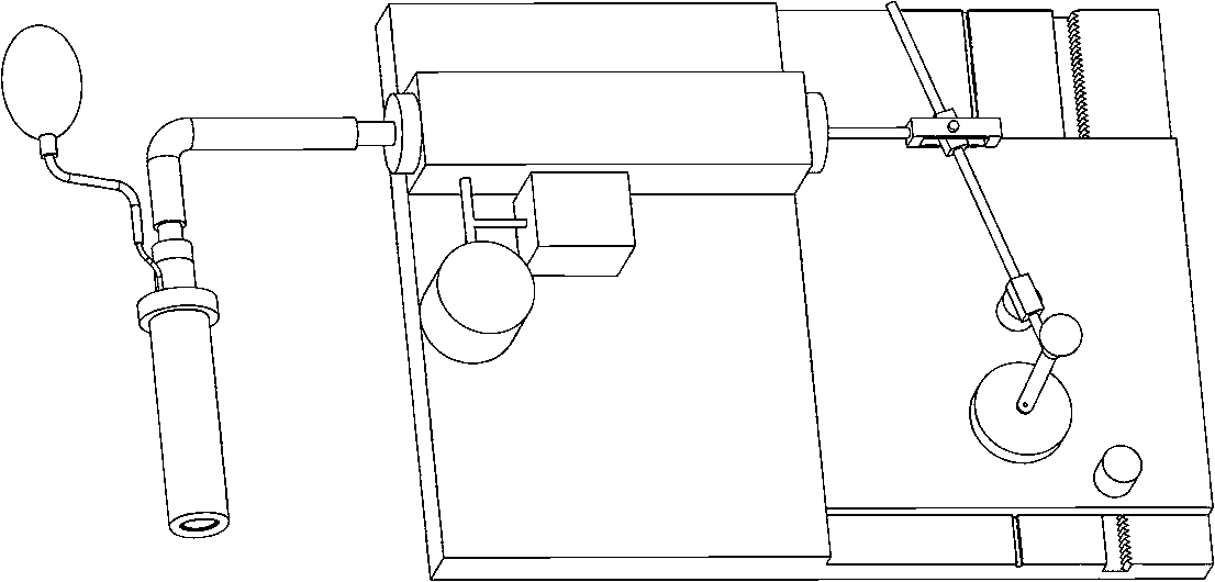
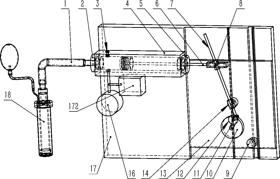
[0087] figure 2 Among them, the stepper motor assembly 9, the motor 10, and the pendulum block 14 are all installed on the carriage 13; the motor 10 drives the crank 11 to rotate, and the crank 11 cooperates with the guide rod 7 through the rotating pair, and the guide rod 7 passes through the hole of the pendulum block 14, Therefore crank 11 can drive guide rod 7 to swing. The guide rod 7 passes through the slide block 8, and the slide block 8 and the right end of the piston rod of the piston assembly 6 form a revolving pair, so that the guide rod 7 can drive the piston assembly 6 to move left and right when it swings left and right.

[0088] Carrier 13 can slide on frame 17, and gear is installed on the stepper motor assembly 9, and this gear and the tooth rack engagement on the frame 17, so stepper motor assembly 9 can control the movement of carriage 13 on frame...

Embodiment 2

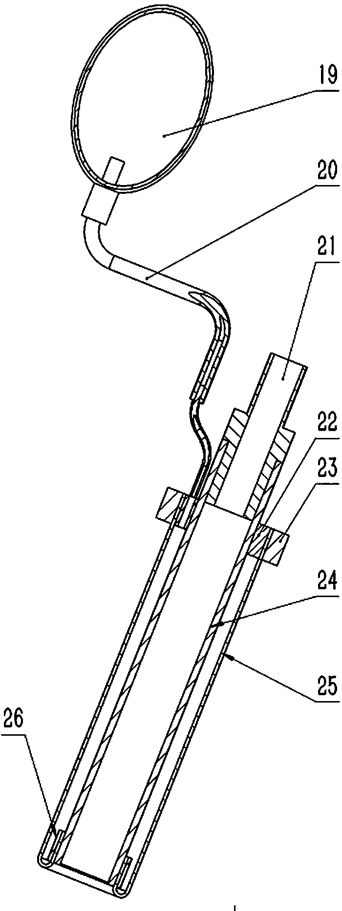
[0102] Figure 8 Shown embodiment 2 is the situation that the present invention is applied to female pelvic floor muscle trainer.

[0103] In use, the resistance member 38 is inserted into the user's vagina.

[0104] The pressure gauge 27 and the air bag 28 are connected to the cavity in the resistance component 38 through the conduit 29 .

[0105] Figure 10 Among them, the airbag cover 42 is made of soft material (such as latex), which is elastic and expandable and deformable. The inner sleeve is also made of a soft material, such as silicone, that compresses inward. Squeeze the air bag 54 repeatedly by hand (that is, Figure 8 The airbag 28 in the airbag), the gas is pressed into the airtight cavity between the outer casing 42 and the inner sleeve 43 of the airbag. During actual operation, the piston assembly 33 is locked and fixed by the control component, so when the airbag 54 is inflated, the inner sleeve 43 cannot be compressed inwardly. When the user feels suitab...

Embodiment 3

[0108] Figure 14 The illustrated embodiment 3 is another situation in which the present invention is applied to a female pelvic floor muscle exerciser (female health care device). The basic situation is similar to Example 2. The difference is moving the damping adjustment parts and check valves to the frame.

[0109] The human body contact end assembly 59, the conduit 57, the damping adjustment assembly 56, and the one-way valve 55 are resistance components.

[0110] The one-way valve 55 and the damping adjustment assembly 56 are connected in parallel, one end is connected to the piston cylinder 64 through the conduit 58 , and the other end is connected to the human body contacting end assembly 59 through the conduit 57 . The air pump 63 is used to inflate the air bag cover 71 of the human body contact end assembly 59 to expand it. The liquid crystal screen 65 can display relevant information such as the liquid pressure applied by the user, the number of exercise times, an...


PUM


Abstract

The invention relates to equipment for a reproductive system, and can be used for solving the problem of treatments for female infertility, male sterility, male nonliquefaction of semen and prostatitis, and relates to the fields of female ovary health care, womb health care, fallopian tube health care, vagina health care, prenatal and postnatal caring and the like. According to the equipment disclosed by the invention, alternate stress is exerted on a female reproductive system cavity channel by fluid to dredge the obstruction of fallopian tubes, and changed pressure is exerted on the wombs, the fallopian tubes and ovaries, so that the effects of massaging, health care and treatment are achieved.

Description

technical field [0001] The invention relates to a device for the reproductive system, which can be used for the treatment of female infertility, non-liquefied male semen, prostatitis, female ovary, uterus, fallopian tube, vaginal health care, prenatal and postnatal care and other fields. Background technique [0002] At present, many women are infertile due to blocked fallopian tubes, premature ovarian failure, and uterine problems. At present, the treatment technology in this area is mainly to dredge with a hard wire, or to use surgery to cut off the blocked part, and then bond the cut off residual part. Since these methods directly destroy the tissue at the blockage of the fallopian tube, it is relatively easy to cause blockage again after dredging. [0003] The treatment of non-liquefied male semen is currently carried out by drugs, with little effect. [0004] Because the ovary is located at the deep position of the human body, it is difficult to massage it with a co...

Claims


Application Information

Patent Timeline
Patent Type & Authority Applications(China)
IPC IPC(8): A61H19/00A61H9/00A61M31/00A61H23/02A61H21/00
CPCA61H9/005A61H9/0078A61H19/44A61H21/00A61H23/02A61H2201/10A61H2201/105A61M31/00A61M2210/1067A61M2210/14A61M2210/005A61B5/00A61H9/00A61H19/00
Inventor 不公告发明人
Owner 李辉
Why Eureka
Try Eureka