Efficient treatment device for gold hydrometallurgy cyanide-containing wastewater

A technology of hydrometallurgy and treatment equipment, which is applied in the field of high-efficiency treatment equipment for cyanide-containing wastewater in gold hydrometallurgy, which can solve the problems of biological and environmental toxicity, high treatment cost, and unsatisfactory treatment effect, and achieve the effect of increasing air content

Inactive Publication Date: 2020-03-24
沈妙萍
View PDF0 Cites 0 Cited by
  • Summary
  • Abstract
  • Description
  • Claims
  • Application Information

AI Technical Summary

Problems solved by technology

[0003] However, gold hydrometallurgy will produce a large amount of cyanide-containing wastewater. Since cyanide-containing wastewater is a highly toxic inorganic wastewater, it has a strong toxic effect on organisms and the environment, and it will produce highly toxic hydrofluoric acid gas under acidic conditions. There is a direct fatal hazard, and it is the waste water that the country compulsorily treats.
Therefore, it is of great practical and social significance to discharge cyanide-containing wastewater up to standard or reuse it for production. However, the treatment efficiency of traditional cyanide-containing wastewater treatment devices is relatively slow, and its treatment effect is not ideal, and Its processing cost is high

Method used


Image

  • Efficient treatment device for gold hydrometallurgy cyanide-containing wastewater
  • Efficient treatment device for gold hydrometallurgy cyanide-containing wastewater
  • Efficient treatment device for gold hydrometallurgy cyanide-containing wastewater

Examples


Embodiment Construction

[0024] The following will clearly and completely describe the technical solutions in the embodiments of the present invention with reference to the accompanying drawings in the embodiments of the present invention. Obviously, the described embodiments are only some, not all, embodiments of the present invention. Based on the embodiments of the present invention, all other embodiments obtained by persons of ordinary skill in the art without making creative efforts belong to the protection scope of the present invention.

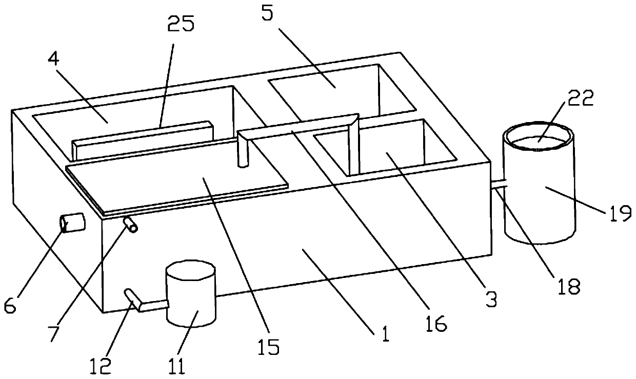
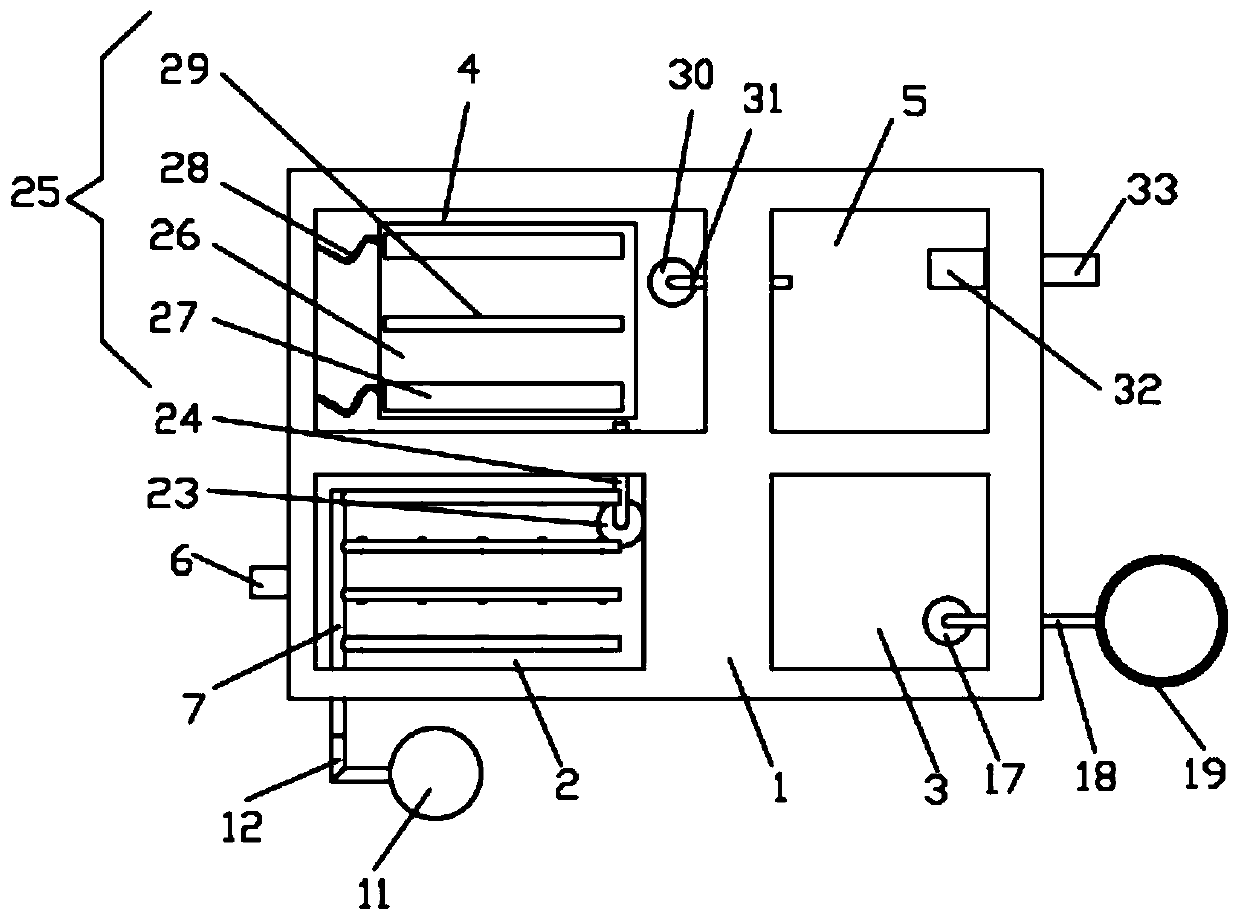
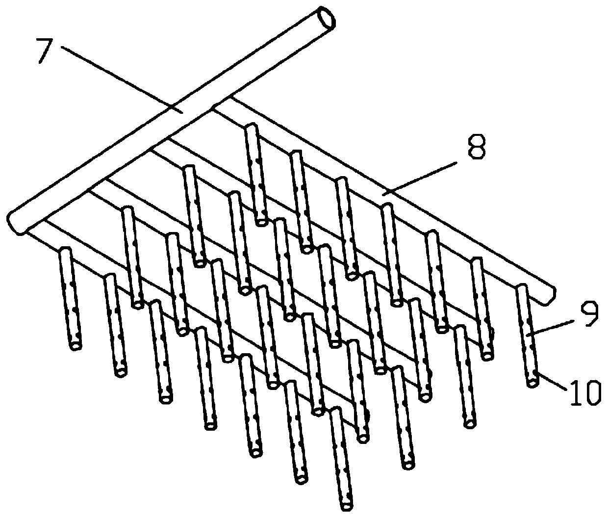
[0025] see Figure 1-6 , the present invention provides a technical solution: a high-efficiency treatment device for gold hydrometallurgy cyanide-containing wastewater, comprising a wastewater treatment device 1 and an acidification pool 2 set on the wastewater treatment device 1, and the wastewater treatment device 1 is a rectangular platform structure , the acidification pond 2 is located at the bottom left of the wastewater treatment device 1, the right sid...


PUM


Abstract

The invention discloses an efficient treatment device for gold hydrometallurgy cyanide-containing wastewater. The device comprises a wastewater treatment device and an acidification pool arranged on the wastewater treatment device; the acidification pool is positioned at the lower left part of the wastewater treatment device; a recovery pool is arranged on the right side of the acidification pool,and an oxidation pool is arranged on the upper side of the acidification pool; a sedimentation pool is arranged on the right side of the oxidation pool; a liquid inlet is formed in the right side ofthe acidification pool; the liquid inlet is connected with a water pump in a wastewater pool through a liquid inlet pipe; a sulfuric acid liquid inlet pipe is arranged on the front side of the acidification pool; a primary water pump is arranged at the bottom of the acidification pool; the primary water pump is connected with the oxidation pool through a primary water conveying pipe; an oxidationflocculation composite bed is arranged at the pool bottom of the oxidation pool, a secondary water pump is arranged on the rear side of the pool bottom of the oxidation pool, and the secondary water pump is connected with the sedimentation pool through a secondary water conveying pipe; sulfuric acid is uniformly distributed to each corner of the acidification pool through a liquid outlet in a vertical liquid conveying pipe, so that the sulfuric acid can uniformly enter from each part of the acidification pool, wastewater in the pool is quickly acidified, and cyanide is acidified into hydrogencyanide gas.

Description

technical field [0001] The invention relates to the technical field of gold hydrosmelting, in particular to a high-efficiency treatment device for cyanide-containing wastewater in gold hydrosmelting. Background technique [0002] Gold hydrometallurgy is the process of contacting ore, concentrated ore enriched by ore dressing or other raw materials with aqueous solution or other liquids, through chemical reactions, etc., so that the metal contained in the raw materials is transferred into the liquid phase, and then the metal contained in the liquid phase is transferred to the liquid phase. It is a method of separating and enriching the contained metals, and finally recovering them in the form of metals or other compounds. It mainly includes unit operation processes such as leaching, liquid-solid separation, solution purification, metal extraction in solution and wastewater treatment. [0003] However, gold hydrometallurgy will produce a large amount of cyanide-containing was...

Claims


Application Information

Patent Timeline
IPC IPC(8): C02F9/04C02F101/18C02F101/20C02F103/16
CPCC02F1/20C02F1/66C02F1/72C02F9/00C02F2001/007C02F2101/18C02F2101/20C02F2103/16
Inventor 沈妙萍
Owner 沈妙萍
Why Eureka
Try Eureka