Laser array, laser light source and laser projection equipment
A laser array and laser light source technology, applied in optics, instruments, optical components, etc., can solve the problems of unfavorable home use, large size, and increased optical path complexity, etc., to reduce the complexity of the structure, reduce the speckle effect, and facilitate miniaturization Effect
- Summary
- Abstract
- Description
- Claims
- Application Information
AI Technical Summary
Problems solved by technology
Method used
Image

Examples
Embodiment 1
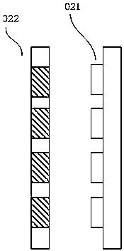
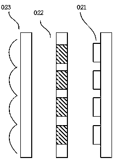
[0042] An embodiment of the present invention provides a laser array, referring to Figure 2A , Figure 2A It is a schematic cross-sectional view of the laser array in the embodiment of the present invention. The laser array in this embodiment includes a light-emitting part 021 for emitting laser beams, and a sealing part 022 is provided along the light-emitting direction of the light-emitting part 021 for transmitting the above-mentioned laser light beam. Specifically, see Figure 3A As shown, the light emitting part 021 includes a light emitting chip 0211 and a metal substrate 0212, and the light emitting chip is connected and fixed on the metal substrate 0212. The light-emitting chip 0211 emits a laser beam under electric drive, wherein the laser beam is linearly polarized light. And, the sealing part 022 includes a first light-transmitting area and a second light-transmitting area, wherein the arrangement of the first light-transmitting area and the second light-transmi...
Embodiment 2
[0088] The present invention also provides a laser light source, such as Figure 8 As shown, it includes a laser array 801, a convergence shaping unit 802, and the convergence shaping unit 802 converges and shapes the laser beam emitted by the laser array 801 to form an illumination beam, which is then homogenized by the homogenization unit 803 and incident into the optical machine. Wherein, the homogenizing part 803 may be a light guide, or may be a fly-eye lens. The shaped laser beam can pass through, for example, a moving diffusion wheel, a diffusion sheet, or a phase adjustment device before being incident on the homogenization unit 803 or after being homogenized by the homogenization unit 803 to dissipate speckles.
[0089]The laser array 801 in this embodiment can be an example of any laser array in the embodiment. Since the laser array is used, the coherence characteristic or speckle effect of the laser beam can be suppressed from the source, and a high-quality illumina...
Embodiment 3
[0091] The present invention also provides a laser projection device, such as Figure 9 As shown, it includes a laser light source 901, a light modulation device 902, and a projection lens 903. The laser light source 901 emits a laser beam to form an illumination beam that irradiates to the light modulation device 902, specifically, to the light modulation device 902. In the DLP architecture, The light modulation device 902 can specifically be a DMD digital micromirror array, including millions of tiny mirrors. The light modulation device 902 modulates the illumination beam according to the driving signal corresponding to the image display signal, and the modulated light beam enters the projection lens for imaging, wherein , the laser light source is the laser light source in the above embodiment. The laser projection device provided in this embodiment can be a laser projector or a laser projection TV, wherein the laser light source can improve the high-quality illumination be...
PUM
| Property | Measurement | Unit |
|---|---|---|
| thickness | aaaaa | aaaaa |
| thickness | aaaaa | aaaaa |
Abstract
Description
Claims
Application Information
 - R&D Engineer
- R&D Manager
- IP Professional
- Industry Leading Data Capabilities
- Powerful AI technology
- Patent DNA Extraction
Browse by: Latest US Patents, China's latest patents, Technical Efficacy Thesaurus, Application Domain, Technology Topic.
© 2024 PatSnap. All rights reserved.Legal|Privacy policy|Modern Slavery Act Transparency Statement|Sitemap