
Anufacturing method of self-aligned quadruple pattern and manufacturing method of semiconductor device

A manufacturing method and self-alignment technology, applied in semiconductor devices, semiconductor/solid-state device components, electric solid-state devices, etc., can solve problems such as high cost, lack of mass production capacity, and inability to realize process nodes, and achieve a reduction in height. , Improve line edge roughness and line width roughness, avoid collapse or skew effect

Active Publication Date: 2020-03-27
YANGTZE MEMORY TECH CO LTD
View PDF6 Cites 0 Cited by
  • Summary
  • Abstract
  • Description
  • Claims
  • Application Information

AI Technical Summary

Problems solved by technology

However, these technologies are costly
Moreover, 193nm immersion lithography technology cannot realize the process node of 14nm and below
Although EUV lithography technology can achieve smaller process nodes, EUV photoresist still faces great difficulties and challenges in terms of resolution, line edge roughness and sensitivity, and has not yet achieved mass production capacity.

Method used


Image

  • Anufacturing method of self-aligned quadruple pattern and manufacturing method of semiconductor device
  • Anufacturing method of self-aligned quadruple pattern and manufacturing method of semiconductor device
  • Anufacturing method of self-aligned quadruple pattern and manufacturing method of semiconductor device

Examples


Embodiment Construction

[0022] In order to make the above-mentioned objectives, features and advantages of the present invention more obvious and understandable, the specific embodiments of the present invention will be described in detail below with reference to the accompanying drawings.

[0023] In the following description, many specific details are set forth in order to fully understand the present invention, but the present invention can also be implemented in other ways different from those described herein, so the present invention is not limited by the specific embodiments disclosed below.

[0024] As shown in the present application and claims, unless the context clearly indicates exceptions, the words "a", "an", "an" and / or "the" do not specifically refer to the singular, but may also include the plural. Generally speaking, the terms "including" and "including" only suggest that the clearly identified steps and elements are included, and these steps and elements do not constitute an exclusive li...


PUM

PropertyMeasurementUnit
thicknessaaaaaaaaaa

Abstract

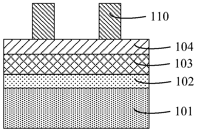
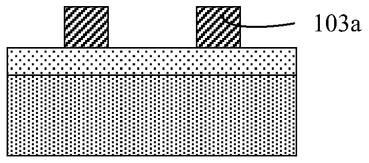
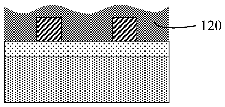
The invention relates to a manufacturing method of a self-aligned quadruple pattern. The manufacturing method comprises: sequentially forming a second core mold layer, a second anti-reflection layer,a first core mold layer and a first anti-reflection layer on a target etching layer; etching the first anti-reflection layer and the first core mold layer to form a first core mold pattern; covering the first core mold pattern with a first side wall material layer; etching the first side wall material layer and the first core mold pattern to form a first side wall; etching part of the thickness ofthe second anti-reflection layer by taking the first side wall as a mask, and forming a groove in an exposed area of the second anti-reflection layer; etching the second anti-reflection layer and thesecond core mold layer to form a second core mold pattern; covering a second side wall material layer on the second core mold pattern; and etching the second side wall material layer and the second core mold pattern to form a second side wall located on the target etching layer. According to the manufacturing method, the line edge roughness and the line width roughness of the semiconductor devicecan be improved.

Description

Technical field [0001] The present invention relates to the field of manufacturing integrated circuits, and in particular to a method for manufacturing a self-aligned quadruple pattern and a method for manufacturing a semiconductor device. Background technique [0002] In the field of integrated circuits, lithography (Lithography) technology is a core part of IC manufacturing, and its main function is to transfer the chip circuit pattern on the mask to the silicon wafer. The photolithography process defines the size of the semiconductor device. Current semiconductor devices have increasingly smaller requirements for critical dimensions. For example, the channel length of field effect transistors has reached the deep sub-micron range. The smaller the feature size, the higher the integration of the chip, the better the performance, and the lower the power consumption. However, as the size shrinks, the influence of the photoresist exposure process on the line edge roughness (LER) ...

Claims


Application Information

Patent Timeline
Patent Type & Authority Applications(China)
IPC IPC(8): H01L23/544G03F9/00
CPCG03F9/7046H01L23/544H01L2223/54426
Inventor 刘峻
Owner YANGTZE MEMORY TECH CO LTD
Learn More