External gear pump and electric lubricating oil pump

An external meshing, gear pump technology, applied in the direction of engine lubrication, turbine/propulsion lubrication, pump, etc., can solve the problems of vibration noise and flow reduction, large reactive power loss, easy heating of oil, etc., to eliminate vibration The effect of reducing noise and flow, improving mechanical efficiency, and reducing friction loss

Pending Publication Date: 2020-03-31
上海尚实航空发动机股份有限公司
View PDF6 Cites 1 Cited by
  • Summary
  • Abstract
  • Description
  • Claims
  • Application Information

AI Technical Summary

Problems solved by technology

[0004] One of the objectives of the present invention is to provide an external gear pump and an electric lubricating oil pump to solve the technical problems of vibration, noise and flow drop caused by cavitation in the prior art
[0005] One of the purposes of the present invention is to provide an external meshing gear pump and an electric lubricating oil pump to solve the technical problems of poor integration, large volume and heavy weight of the electric lubricating oil pump in the prior art
[0006] One of the purposes of the present invention is to provide an external gear pump and an electric lubricating oil pump to solve the technical problems of large reactive power loss and easy heating of oil in the prior art

Method used


Image

  • External gear pump and electric lubricating oil pump
  • External gear pump and electric lubricating oil pump
  • External gear pump and electric lubricating oil pump

Examples


Embodiment Construction

[0035] The following will clearly and completely describe the technical solutions in the embodiments of the present invention with reference to the accompanying drawings in the embodiments of the present invention. Obviously, the described embodiments are only some, not all, embodiments of the present invention. Based on the embodiments of the present invention, all other embodiments obtained by persons of ordinary skill in the art without creative efforts fall within the protection scope of the present invention.

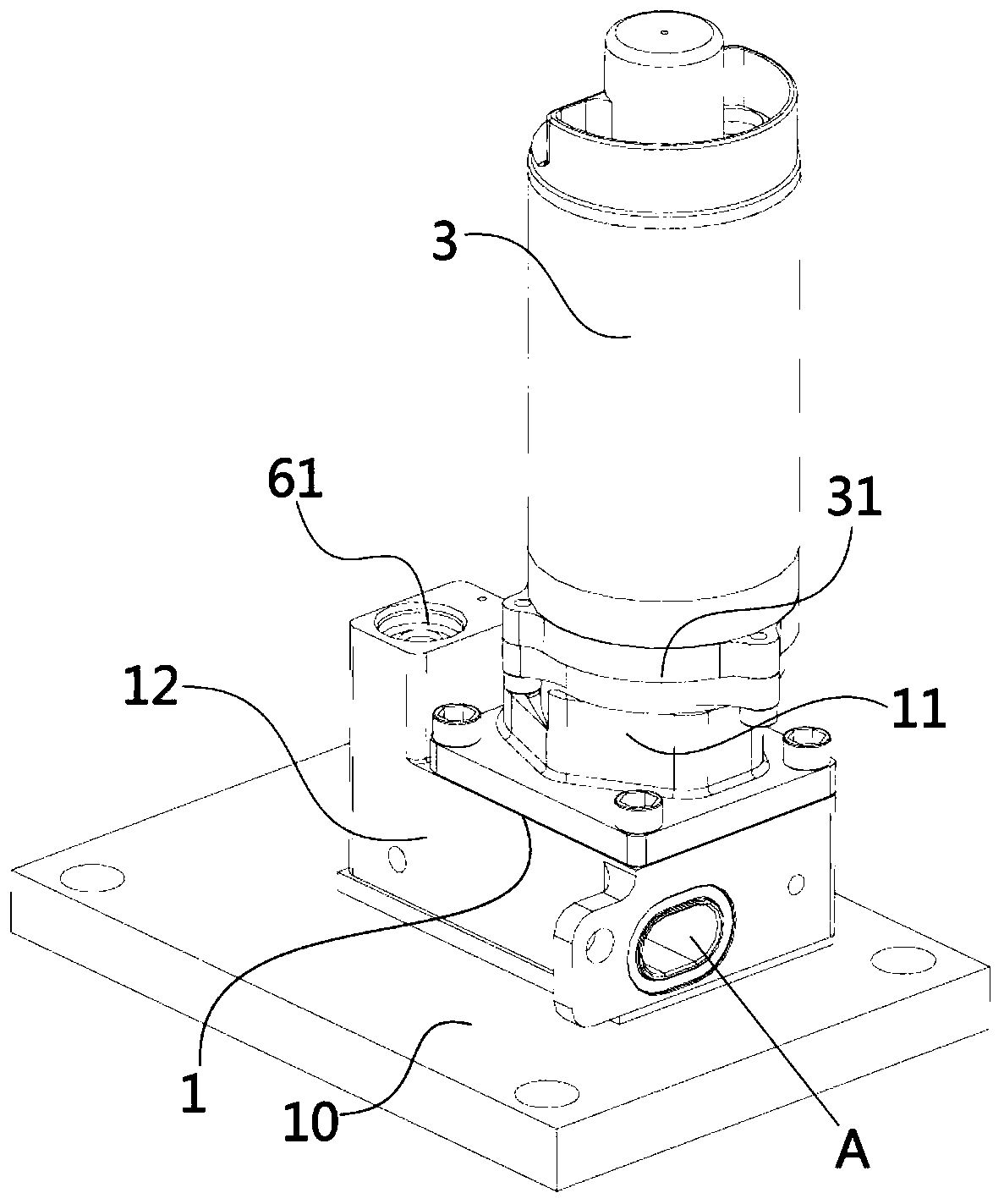
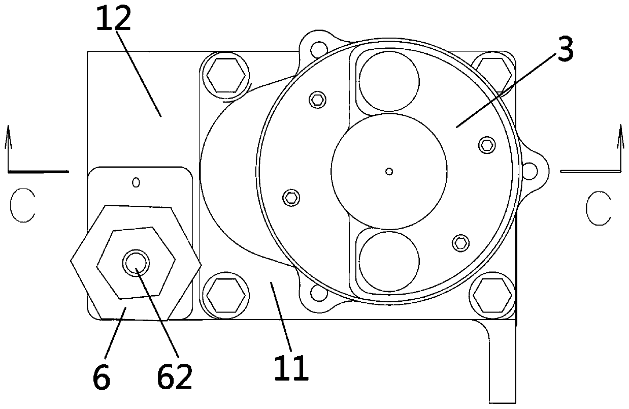
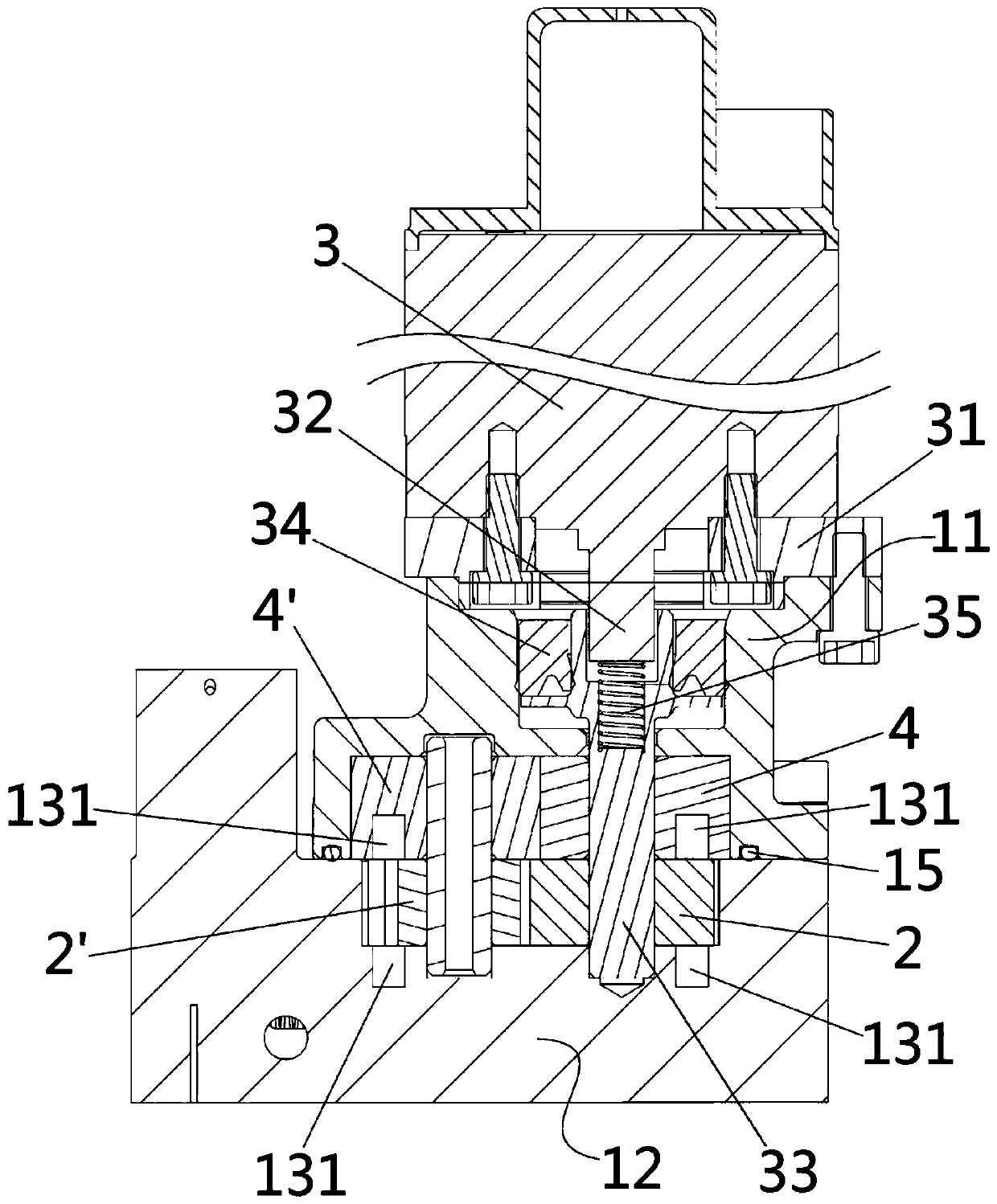
[0036] Such as Figure 1 to Figure 8 As shown, the present invention provides an electric lubricating oil pump, which includes an external gear pump 1 and a mounting plate 10, and the external gear pump 1 is mounted on the mounting plate 10 by screws; wherein, the external gear pump includes a pump casing body 1', a gear 2 and a motor 3 which are arranged in the pump housing 1' and engage with each other;

[0037] Specifically, the pump housing 1' includes an uppe...


PUM


Abstract

The invention discloses an external gear pump and an electric lubricating oil pump. The electric lubricating oil pump includes the external gear pump and an installation plate. The external gear pumpis arranged on the installation plate through a screw. The external gear pump includes a pump shell with a pump chamber formed through buckling an upper shell and a lower shell, and two gears which are externally meshed with each other and are arranged in the pump chamber through bearings. The gears are driven to rotate by a motor. An end surface of the pump chamber includes an oil inlet groove,and the oil inlet groove is extended along a rim direction of each gear and is superposed with gear teeth of at least part of the gears on the side of an oil inlet cavity. At least one side of each gear is provided with the oil inlet groove, and the oil inlet groove is connected with an oil inlet pipeline. By adopting methods of supplementing oil from the side of the gear and supplementing oil through a tooth crest superposition mode, an area of the oil inlet cavity is increased, oil intake of a single tooth crest direction is reduced, and an insufficient filling phenomenon of lubricating oilcaused by a radial centrifugal force is avoided. A vibration noise and flow drop caused by cavitation are eliminated, and power losses of the electric lubricating oil pump are reduced.

Description

technical field [0001] The invention relates to the technical field of machinery, in particular to an external gear pump, in particular to an electric lubricating oil pump used in a lubricating oil system of a gas turbine engine. Background technique [0002] At present, most gas turbine engines use circulating lubricating oil systems, which use lubricating oil to cool and lubricate key components to increase their life and ensure the normal operation of core components. [0003] The lubricating oil pump is the power source for lubricating oil pressurization and delivery in the lubricating oil system, and is a key component of the lubricating oil system. Especially in the field of aviation, due to its extremely harsh working environment and performance requirements, it has always been a technical problem to ensure its environmental adaptability and performance stability. When the traditional external gear lubricating oil pump is running at high speed, the lubricating oil is...

Claims


Application Information

Patent Timeline
Patent Type & Authority Applications(China)
IPC IPC(8): F04C2/18F04C15/00F04C14/24F04C11/00F02C7/06F16N13/20
CPCF04C2/18F04C2/082F04C2/084F04C15/00F04C14/24F04C11/008F02C7/06F16N13/20F04C2240/50F16N2210/02
Inventor 黄啸王石柱
Owner 上海尚实航空发动机股份有限公司
Why Eureka
Try Eureka