Precombustion system with gas-carried nozzle, internal combustion engine and precombustion control method

A gas nozzle and nozzle technology, applied in the engine field, can solve problems such as cost increase, difficulty in achieving lean combustion, and cylinder head space limitation, and achieve the effects of simplifying the structure, eliminating residual exhaust gas, improving stability and precise control

Pending Publication Date: 2020-04-03
天津轩云科技有限公司
View PDF0 Cites 6 Cited by
  • Summary
  • Abstract
  • Description
  • Claims
  • Application Information

AI Technical Summary

Problems solved by technology

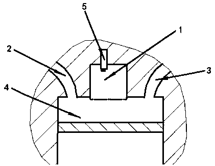
The first structure is as figure 1 As shown, since the spark plug is only arranged in the pre-combustion chamber, the exhaust gas in the pre-combustion chamber cannot be completely discharged after the primary combustion is completed, and the fuel (oil / gas) and air are not easy to enter the pre-combustion chamber, so it is difficult to achieve lean combustion, and even combustion is difficult risk, so it is only suitable for a narrow range of internal combustion engine operating conditions
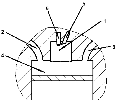
The second structure is as figure 2 As shown, since the spark plug and fuel injector are only arranged in the pre-chamber, although the problem of fuel supply to the pre-chamber is solved after the first combustion, the exhaust gas still cannot be completely discharged, and the air is also difficult to enter the pre-chamber, and it is also difficult to To achieve lean combustion, there is combustion difficulty in idling and cold start conditions, especially not suitable for internal combustion engines with equivalence ratio combustion using 3-way catalytic aftertreatment devices
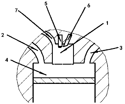
However, the pre-chamber intake port is added to the pre-chamber, and the pre-chamber intake port also needs to be separately controlled, which will lead to an oversized structure and high system complexity. Not only the cost is greatly increased, but also the required cylinder head Excessive space limits its usability

Method used


Image

  • Precombustion system with gas-carried nozzle, internal combustion engine and precombustion control method
  • Precombustion system with gas-carried nozzle, internal combustion engine and precombustion control method
  • Precombustion system with gas-carried nozzle, internal combustion engine and precombustion control method

Examples


Embodiment Construction

[0029] It should be noted that, in the case of no conflict, the embodiments of the present invention and the features in the embodiments can be combined with each other.

[0030] In describing the present invention, it should be understood that the terms "center", "longitudinal", "transverse", "upper", "lower", "front", "rear", "left", "right", " The orientations or positional relationships indicated by "vertical", "horizontal", "top", "bottom", "inner" and "outer" are based on the orientations or positional relationships shown in the drawings, and are only for the convenience of describing the present invention and Simplified descriptions, rather than indicating or implying that the device or element referred to must have a particular orientation, be constructed and operate in a particular orientation, and thus should not be construed as limiting the invention. In addition, the terms "first", "second", etc. are used for descriptive purposes only, and should not be understood ...


PUM


Abstract

The invention discloses a precombustion system with a gas-carried nozzle. The system comprises a precombustion chamber, a gas-carried nozzle mechanism, an ignition mechanism and a control mechanism; through arrangement of the gas-carried nozzle mechanism, the fuel and air mixing can be realized, and mixed gas is sprayed into the precombustion chamber to solve the problems of waste gas emission andfuel and air supply; and a precombustion chamber intake way and related structures have no need to be added in the precombustion chamber to greatly simplify the structure of the precombustion chamber. The invention provides the precombustion system with the gas-carried nozzle; and through arrangement of the control system, the control of the fuel mixing quantity, the compressed air mixing quantity, the mixed gas spraying time and the spraying lasting period in the gas-carried nozzle mechanism can be realized, and residual waste gas in the precombustion chamber can be eliminated, so that the stability and the precise control of ignition and combustion are improved, high efficiency from idle speed to highest rotating speed and from low load to full load is achieved, and the internal combustion engine works in the combustion process with high performance and low emission.

Description

technical field [0001] The invention belongs to the technical field of engines, in particular to a pre-combustion system with an air-entrapped nozzle, an internal combustion engine and a pre-combustion control method. Background technique [0002] There are three ways to arrange the structure of the existing internal combustion engine with a pre-combustion chamber. The first is to arrange only spark plugs in the pre-combustion chamber; the second is to arrange spark plugs and fuel injectors in the pre-combustion chamber; the third is to arrange Spark plugs, fuel injection pump and pre-chamber intake. The first structure is as figure 1 As shown, since the spark plug is only arranged in the pre-combustion chamber, the exhaust gas in the pre-combustion chamber cannot be completely discharged after the primary combustion is completed, and the fuel (oil / gas) and air are not easy to enter the pre-combustion chamber, so it is difficult to achieve lean combustion, and even combusti...

Claims


Application Information

Patent Timeline
Patent Type & Authority Applications(China)
IPC IPC(8): F02B19/10F02B19/16F02M29/00F02D41/30
CPCF02B19/10F02B19/16F02D41/30F02M29/00Y02T10/12
Inventor 岳锋飞张浩凡刘付勇朱敬锋
Owner 天津轩云科技有限公司
Why Eureka
Try Eureka