
Collector heat dissipation structure for radiant cooling type space traveling-wave tube

A heat dissipation structure and collector technology, applied in the field of collector heat dissipation structure, can solve problems such as pollution of energy transmission devices, power output, efficiency and life damage, temperature rise of traveling wave tubes, etc., to achieve simple structure of heat dissipation structure and realizable process The effect of good resistance and strong mechanical resistance

Active Publication Date: 2020-04-07
NANJING SANLE GROUP
View PDF8 Cites 3 Cited by
  • Summary
  • Abstract
  • Description
  • Claims
  • Application Information

AI Technical Summary

Problems solved by technology

If the heat generated by the traveling wave tube cannot be dissipated in a timely and effective manner, it will cause a high temperature rise of the traveling wave tube itself. The collector is the main heat-generating part of the traveling wave tube. From the collector, if the temperature of the collector is too high, part of the heat flow will be transferred back to the high-frequency structure of the traveling wave tube, which will eventually affect the reliability and stability of the tube, and cause a certain degree of damage to its power output, efficiency and life. destroy
For example, when the temperature of the collector reaches 500°C, a large amount of electrode materials in the collector will easily evaporate to the ceramic insulating connector, thereby reducing the insulation between the high-frequency structure and the collector, and in severe cases, it may cause a short circuit; It may damage the seal of the packaging part and pollute the energy transmission device, resulting in shortened or damaged traveling wave tube life; too high collector temperature may also cause more secondary electrons to overflow and accelerate bombardment to the high-voltage electrode, resulting in collector efficiency reduce
If the temperature of the high-frequency structure is too high, the thermal stress may exceed the safe operating area, causing physical damage to the interacting circuit
For example, the rupture of the helix will cause an open circuit for the slow wave interaction, and the rupture of the clamping rod will cause small disturbances in the slow wave structure, both of which can cause the TWT to fail.

Method used


Image

  • Collector heat dissipation structure for radiant cooling type space traveling-wave tube
  • Collector heat dissipation structure for radiant cooling type space traveling-wave tube
  • Collector heat dissipation structure for radiant cooling type space traveling-wave tube

Examples


Embodiment Construction

[0018] In order to further understand the content of the present invention, the present invention will be described in detail in conjunction with the accompanying drawings and embodiments.

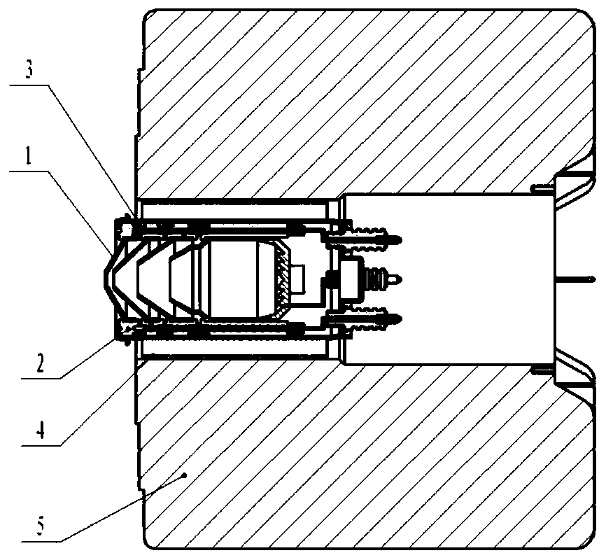
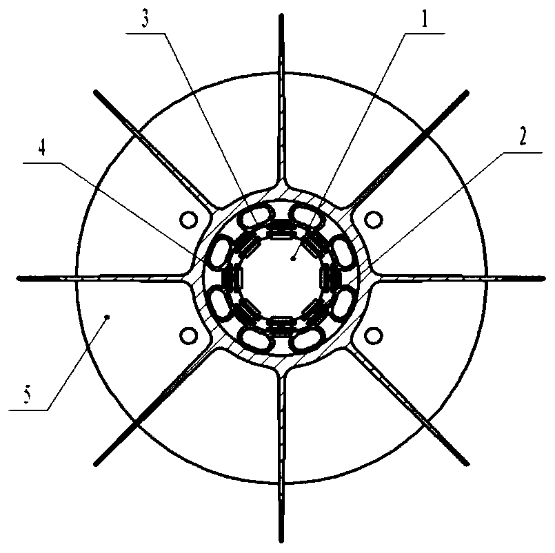
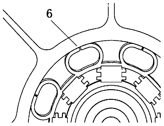
[0019] A collector heat dissipation structure for a radiation-cooled space traveling wave tube described in this embodiment, such as Figure 1-3 As shown, the collector has a four-stage step-down design. The collector electrode and the beryllium oxide insulating ceramic plate are welded and fixed. The periphery of each electrode is welded and connected by 8 independent insulating ceramic plates. The inner wall of the outer cylinder of the collector is equipped with Slots for locating and welding insulating porcelain plates; 8 separate copper “O” rings welded outside the outer collector cylinder.

[0020] Such as Figure 4-5 As shown, the heat radiator is designed as a one-piece structure, and the material is aluminum alloy, including a cylindrical core column, 8 fins, and side plates conn...


PUM


Abstract

The invention discloses a collector heat dissipation structure for a radiant cooling type space traveling-wave tube. A collector comprises a collector electrode, an insulating porcelain plate and a collector outer cylinder; the collector electrode is a cylinder; a plurality of insulating porcelain plates are uniformly fixed on the outer cylindrical surface; and the collector outer cylinder surrounds the cylindrical surface of the collector electrode, the inner wall of the collector outer cylinder is provided with fixing grooves in one-to-one correspondence with the insulating porcelain plates,the heat dissipation structure comprises a plurality of O-shaped rings and a heat radiator surrounding the collector outer cylinder, the outer circumference of the collector outer cylinder is uniformly and fixedly provided with the plurality of O-shaped rings, and the outer edge of each O-shaped ring is fixed on the inner wall of the heat radiator. The structure is simple, the mechanical resistance is high, the reliability is good, the process realizability is good, and the working requirement of the long-life space traveling-wave tube can be met.

Description

technical field [0001] The invention relates to a collector heat dissipation structure for a radiation-cooled space traveling wave tube. Background technique [0002] The outer space environment in which space traveling wave tubes work is very harsh. When the communication satellite faces the sun, the temperature reaches hundreds of degrees Celsius, and when it faces away from the sun, the temperature drops to more than minus 50 degrees Celsius. It also has to withstand the continuous bombardment of various high-energy particles in the universe. . Space traveling wave tubes, like various electronic devices carried on satellite platforms, must meet the requirements of high efficiency, reliability, and long life. If the heat generated by the traveling wave tube cannot be dissipated in a timely and effective manner, it will cause a high temperature rise of the traveling wave tube itself. The collector is the main heat-generating part of the traveling wave tube. From the colle...

Claims


Application Information

Patent Timeline
IPC IPC(8): H01J23/033
CPCH01J23/033
Inventor 陈平何金梅孙萌成红霞董笑瑜刘逸群
Owner NANJING SANLE GROUP
Learn More