Disc type dragging and power generation integrated pulse power supply system

A pulsed power supply, integrated technology, applied in electrical components, electromechanical devices, electric components and other directions, can solve the problems of low energy storage density and power density, low system compactness, high noise, etc., to improve energy storage density, reduce Noise, impact reduction effect

Active Publication Date: 2020-04-07
HARBIN INST OF TECH
View PDF7 Cites 1 Cited by
  • Summary
  • Abstract
  • Description
  • Claims
  • Application Information

AI Technical Summary

Problems solved by technology

[0005] The purpose of the present invention is to solve the current problems of axial placement of two motors, long shafting, large vibration and noise, low system compactness, low energy storage density and power density, and to provide a disc-type drive and power generation Integrated Pulse Power System

Method used


Image

  • Disc type dragging and power generation integrated pulse power supply system
  • Disc type dragging and power generation integrated pulse power supply system
  • Disc type dragging and power generation integrated pulse power supply system

Examples


specific Embodiment approach 1

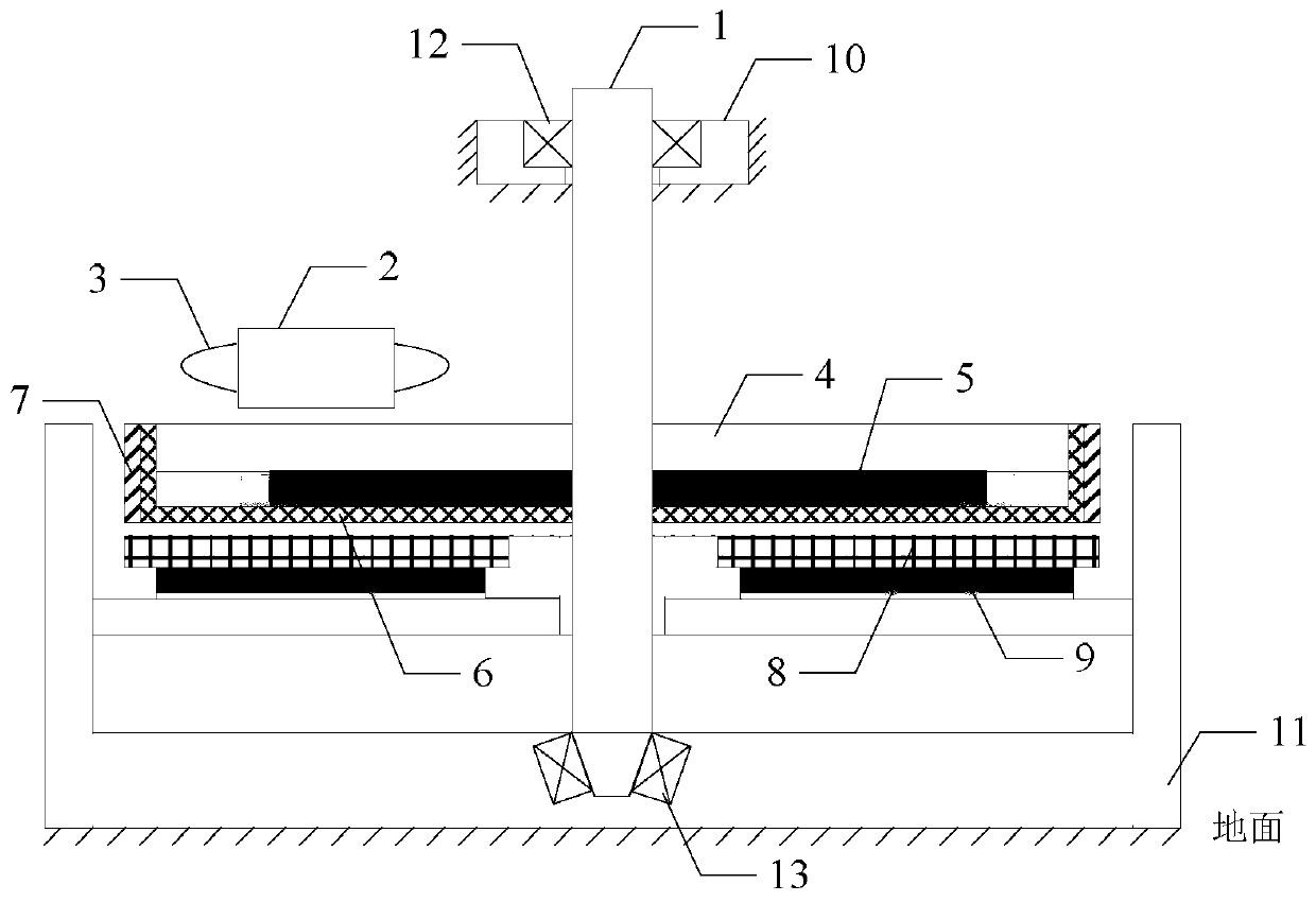
[0024] Specific implementation mode one: combine Figure 1 to Figure 3 Describe this embodiment, a disc drive and power generation integrated pulse power supply system described in this embodiment is characterized in that the integrated pulse power supply system includes an upper stator, a rotor, a lower stator, a fixing device 10, a fixing platform 11. Ball bearing 12 and tapered bearing 13;

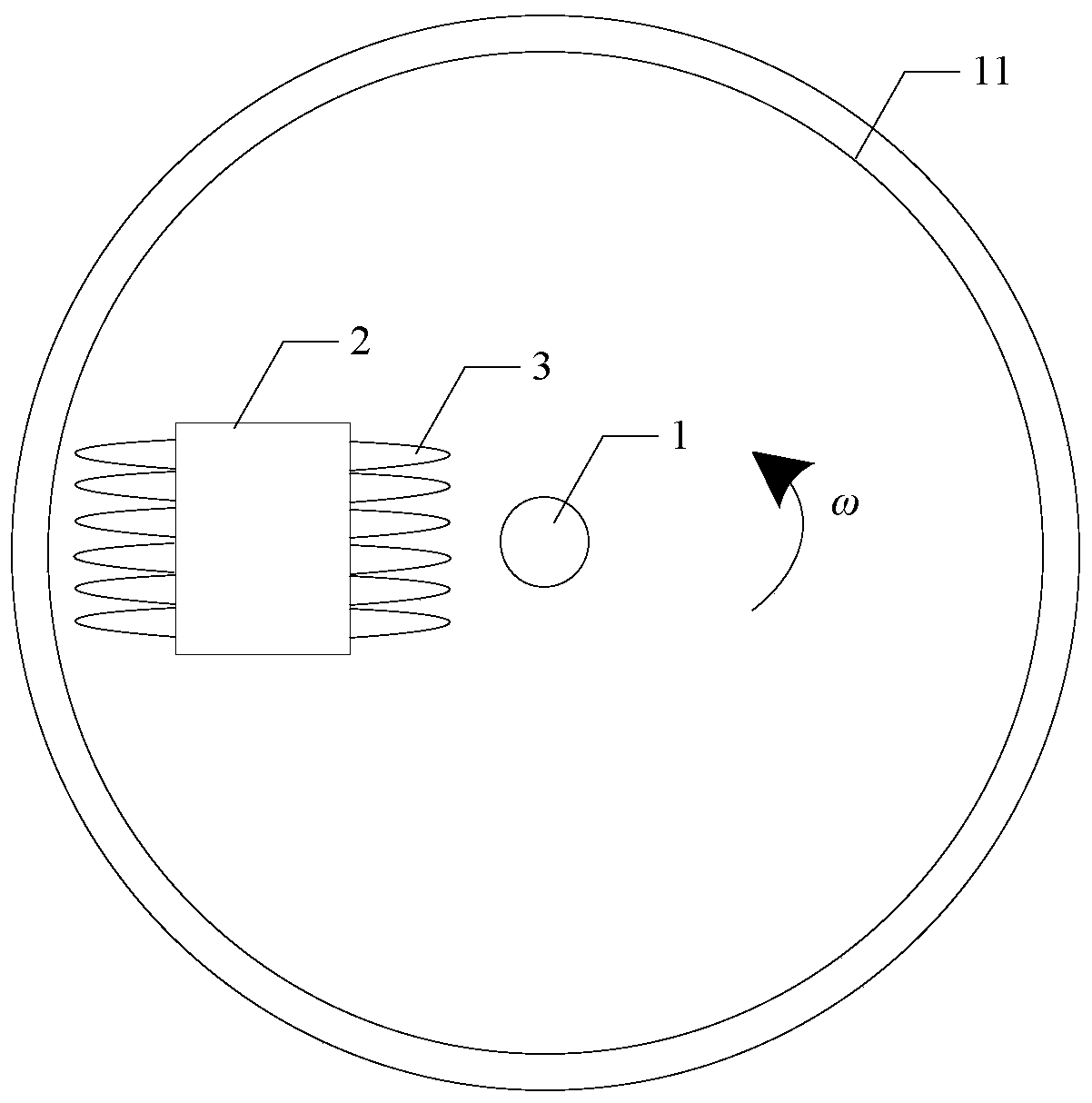
[0025] The upper stator includes a No. 1 stator yoke 2 and a motor stator winding 3;

[0026] The rotor includes a rotating shaft 1, an energy storage flywheel 4, a permanent magnet 5, a compensating element 6 and a rotor bandage 7;

[0027] The lower stator includes an armature winding 8 and a second stator yoke 9;

[0028] The outer ring of the tapered bearing 13 is fixed in the fixed platform 11, the outer ring of the ball bearing 12 is fixed in the fixing device 10, and the two ends of the rotating shaft 1 are respectively fixed on the inner ring of the tapered bearing 13 and the ...

specific Embodiment approach 2

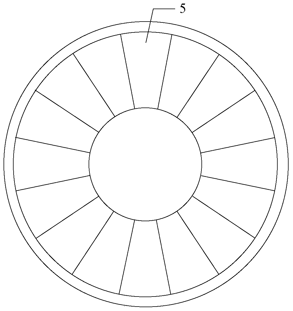
[0036] Specific implementation mode two: combination Figure 4 Describe this embodiment, this embodiment is to further limit a kind of disk drive and power generation integrated pulse power supply system described in the first embodiment, in this embodiment, the permanent magnet 5 is a Halbach permanent magnet array structure .

specific Embodiment approach 3

[0037] Specific Embodiment 3: This embodiment is to further limit the disk drive and power generation integrated pulse power supply system described in Embodiment 1 or 2. In this embodiment, the motor stator winding 3 and the permanent magnet 5 The air gap magnetic density generated is axial.


PUM


Abstract

The invention discloses a disc type dragging and power generation integrated pulse power supply system, belongs to the technical field of inertia energy storage pulse power supplies, and aims to solvethe problems of long shafting, large vibration and noise, low system compactness, low energy storage density and low power density due to the fact that two motors are axially arranged at present. A conical bearing is arranged in a fixed platform, a ball bearing is arranged in a fixed device, and a rotating shaft is fixed on the conical bearing and the ball bearing; and upper air gaps are formed between the rotor and the upper stators, the number of the upper stators and the distance between the upper air gaps are respectively adjustable, and lower air gaps are formed between the rotor and thelower stators. An energy storage flywheel is fixed on the rotating shaft, and a permanent magnet is arranged on the surface of the energy storage flywheel; the compensation element is arranged belowthe permanent magnet; a rotor bandage is wound on the surface of a compensation element; the rotating shaft penetrates through a central hole; an armature winding is placed on a stator yoke, and is adischarge end; and the motor stator winding is wound on the stator yoke, and the motor stator winding is a charging end. The beneficial effects are that the charging speed is adjustable, and discharging is protected.

Description

technical field [0001] The invention belongs to the technical field of inertial energy storage pulse power supply. Background technique [0002] High-power pulse power supply can provide short-term strong pulse current, which has important applications in military, semiconductor, industry, environmental protection and other fields; pulse generator based on inertial energy storage is a special synchronous generator, using compensation principle and magnetic Through the compression principle, the internal inductance of the armature winding is greatly reduced, thereby obtaining a pulse current with a very high amplitude, which has great application potential. [0003] The existing generator system is driven by a separate prime mover (motor). The generator and the motor are arranged axially and connected by a coupling. The shaft system of the whole system is long, which is easy to cause vibration and large mechanical noise. It is difficult to disengage the engine and prime move...

Claims


Application Information

Patent Timeline
Patent Type & Authority Applications(China)
IPC IPC(8): H02K7/02H02K7/08H02K1/27
CPCH02K1/2793H02K7/02H02K7/083H02K2201/03H02K2213/09Y02E60/16
Inventor 吴绍朋吴松霖周锦阳张品佳
Owner HARBIN INST OF TECH
Why Eureka
Try Eureka