Supercharge Your Innovation With Domain-Expert AI Agents!

Ultrasonic cutting device and using method thereof

A cutting device and ultrasonic technology, applied in metal processing, stone processing tools, manufacturing tools, etc., can solve the problems of long adjustment time of coaxiality, low reliability, large structure occupied space, etc., and improve the surface roughness of workpiece processing. The effect of improving the drilling efficiency and improving the service life

Pending Publication Date: 2020-04-14
SHENYANG YUANDA SCI & TECH PARK +1
View PDF0 Cites 2 Cited by
  • Summary
  • Abstract
  • Description
  • Claims
  • Application Information

AI Technical Summary

Problems solved by technology

Compared with the non-contact electric field and magnetic field induction method, the current transmission method of the slip ring contact method takes up a lot of space, and it is difficult to realize the current transmission during the high-speed operation of the contact spindle, and the reliability is not high.
With the existing electromagnetic induction technology, the installation needs to destroy the main shaft structure, and it takes a long time to adjust the coaxiality of the input coil and output coil when installing, which cannot guarantee the coaxial requirements of the input coil and output coil, and the power transmission efficiency is low
So far, there is no better solution

Method used


Image

  • Ultrasonic cutting device and using method thereof
  • Ultrasonic cutting device and using method thereof
  • Ultrasonic cutting device and using method thereof

Examples


no. 1 example

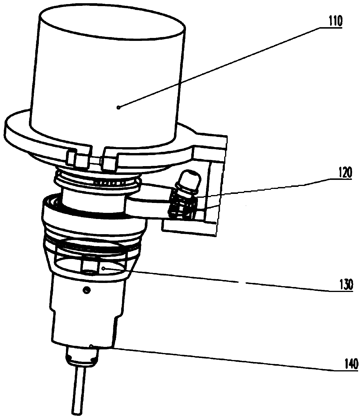
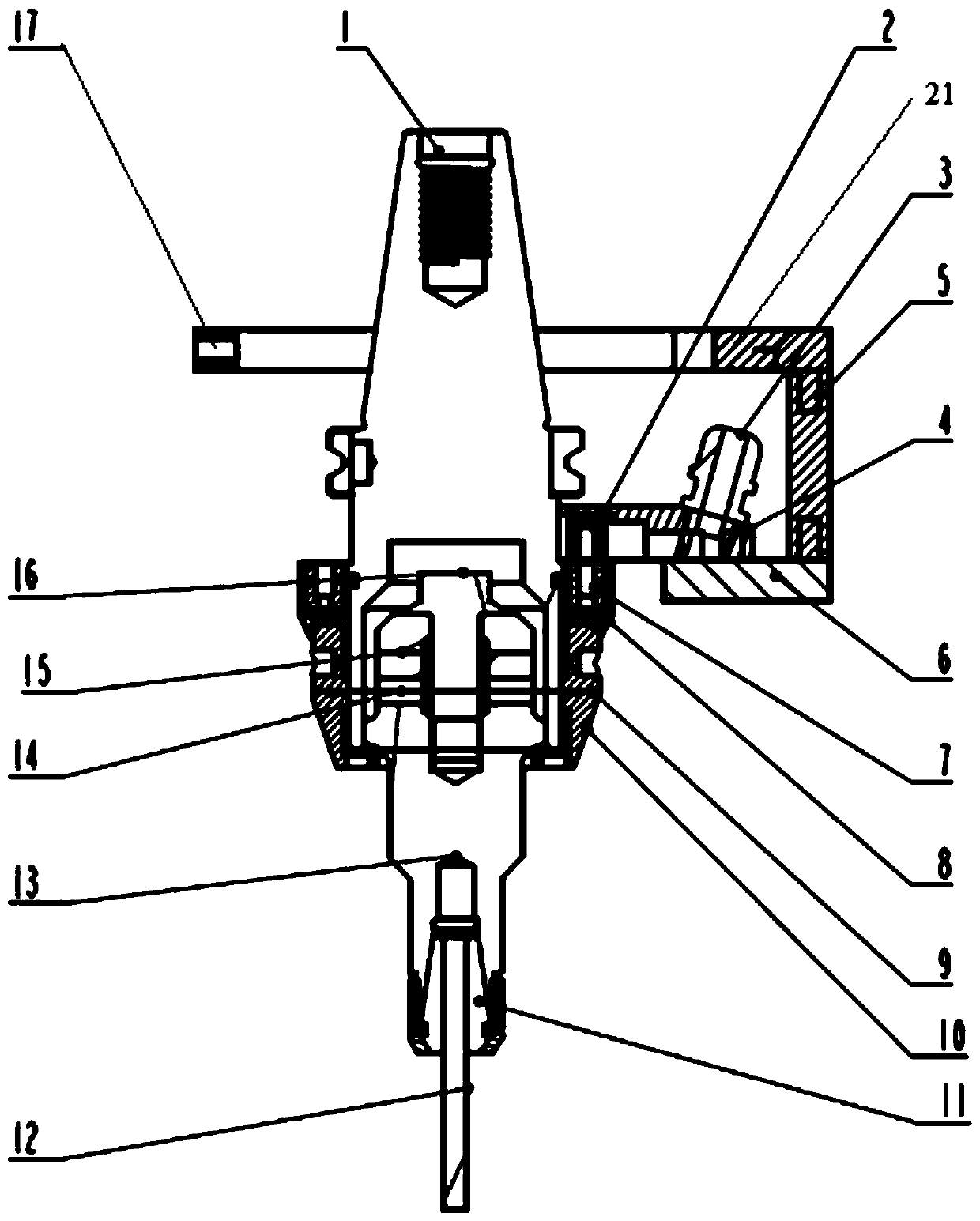
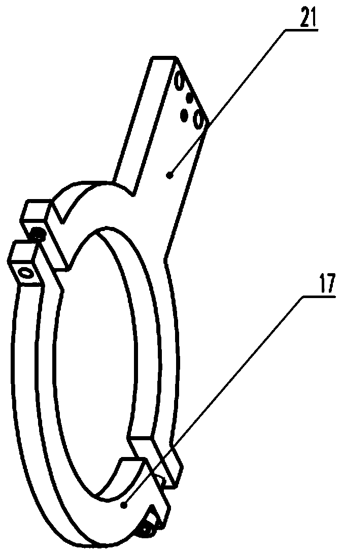
[0037] The appearance of the ultrasonic cutting device of the present invention is as follows: figure 1 As shown, it includes a spindle interface module 110 , a power transmission module 120 , an ultrasonic generation module 130 , and a tool holding module 140 . Among them, such as figure 2 As shown, the spindle interface module 110 includes a tool holder 1 , a radial connecting plate 6 , an axial connecting plate 5 , a first fixing ring 17 , and a second fixing ring 21 . Wherein, the handle 1 is tapered, and its small diameter end is coaxially connected with the rotating spindle of the machine tool through a broach mechanism, and rotates at high speed simultaneously with the spindle. like image 3 As shown, the first fixed ring 17 and the second fixed ring 21 are semicircular, and there are radial bolt holes at both ends of the first fixed ring 17 and the second fixed ring 21 respectively. The first fixed ring 17 and the second fixed ring The fixing ring 21 is fastened on...


PUM


Abstract

An ultrasonic cutting device and a using method thereof are disclosed, the ultrasonic cutting device comprises a knife handle used for being coaxially connected with a main shaft, and a first fixing ring and a second fixing ring buckled on the outer side of the main shaft, an axial connecting plate extending in the axial direction from the radial outer end of the second fixing ring, a radial connecting plate extending inwards in the radial direction from the position, away from the second fixing ring, of the axial connecting plate, an input coil base installed at the end, close to the knife handle, of the radial connecting plate, wherein the input coil base is in a fan shape coaxial with the knife handle and an input coil is installed at the end, close to the knife handle, of the input coil base, an output coil base in a circular ring shape and coaxially fixed to the outer wall of the knife handle, wherein an output coil and a conductive spacer, an energy converter and an amplitude-change pole in the knife handle are installed in the output coil base and the conductive spacer is electrically connected with the output coil, and a tool chuck installed on the amplitude-change pole andclamping a cutter. The drilling efficiency and precision are improved. The coaxiality and the axial clearance of the input coil and the output coil can be adjusted.

Description

technical field [0001] The invention relates to the technical field of ultrasonic equipment, in particular to an ultrasonic cutting device and a method for using the same. Background technique [0002] Ultrasonic assisted cutting technology is a technology developed internationally in the past ten years. Ultrasonic assisted cutting can more effectively cut reinforced composite materials (such as glass fiber, resin-based carbon fiber, Kevlar fiber, paper-based or aluminum base honeycomb material) and brittle and hard materials such as ceramics, sapphire, and glass. Different from the traditional cutting process, the core of ultrasonic cutting technology is ultrasonic cutting. The basic principle is to use an ultrasonic power supply to generate ultrasonic waves with a frequency of 20kHz to 30kHz through the transducer built in the tool to convert the original ultrasonic vibration with a small amplitude and frequency into mechanical vibration of the same frequency, and then ob...

Claims


Application Information

Patent Timeline
Patent Type & Authority Applications(China)
IPC IPC(8): B26D7/08B26D7/26B26D1/12B28D1/22
CPCB26D1/12B26D7/086B26D7/2614B26D7/2628B28D1/22
Inventor 柳耀阳韩旭孟宪林刘斌双曹阳
Owner SHENYANG YUANDA SCI & TECH PARK
Features
  • R&D
  • Intellectual Property
  • Life Sciences
  • Materials
  • Tech Scout
  • Unparalleled Data Quality
  • Higher Quality Content
  • 60% Fewer Hallucinations
Learn More