Automatic feeding and discharging device for pipe cutting machine and working method thereof

An automatic loading and unloading technology, which is applied in applications, home appliances, manufacturing tools, etc., can solve the problems of horizontal direction error of deformed pipes, uncontrollable range of cutting error values, poor compatibility of large and heavy pipes, etc. The effect of improving product quality, reducing product error and reducing energy consumption

Pending Publication Date: 2020-04-17
苏州松谷智能装备股份有限公司
View PDF0 Cites 6 Cited by
  • Summary
  • Abstract
  • Description
  • Claims
  • Application Information

AI Technical Summary

Problems solved by technology

[0004] 1. Due to the problem of the material of the belt, the uncontrollable amount of deformation will lead to errors in the horizontal direction of the pipe. When switching between various pipes, it takes a long period of pre-adjustment, and the long-term work wears quickly and the life is short;
[0005] 2. Due to the single-arm single-motor control, there are mechanical errors in the synchronization of multiple reclaiming arms during use, and the uncontrollable range of cutting error values ​​is wide
The independent blanking landslide rack will have the following problems: due to the simple structure, the blanking is relatively close to the processing area during use, and the blanking mechanism has no slag and dust removal structure, which will cause sputtering of molten slag and stick to the finished parts surface, affecting product quality
However, the material receiving and blanking mechanism with floating rollers will have the following problems: the early installation is more troublesome, and the compatibility with some large and heavy pipes is poor, and it is only suitable for some small or medium-sized pipes

Method used


Image

  • Automatic feeding and discharging device for pipe cutting machine and working method thereof
  • Automatic feeding and discharging device for pipe cutting machine and working method thereof
  • Automatic feeding and discharging device for pipe cutting machine and working method thereof

Examples


Embodiment 1

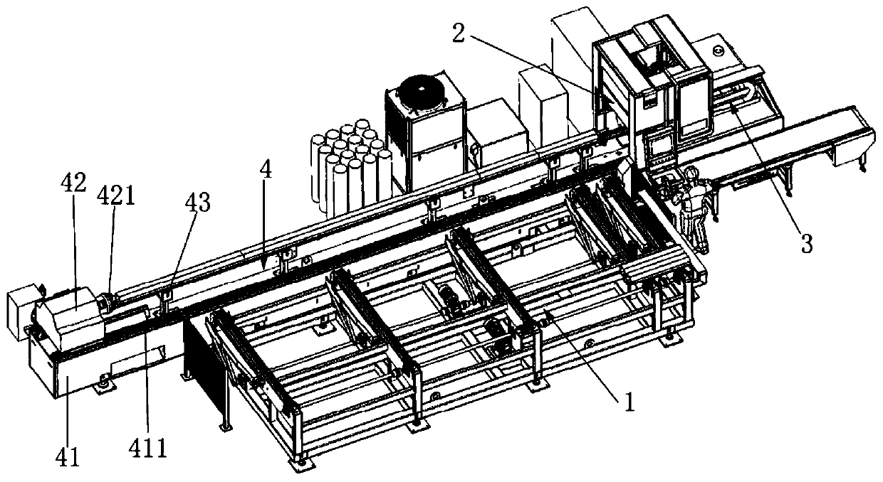
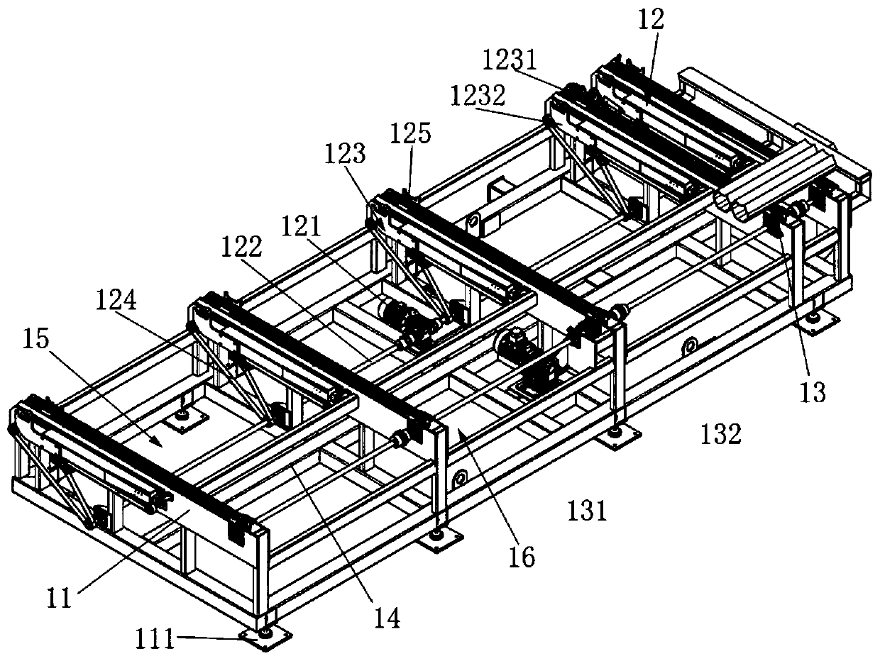
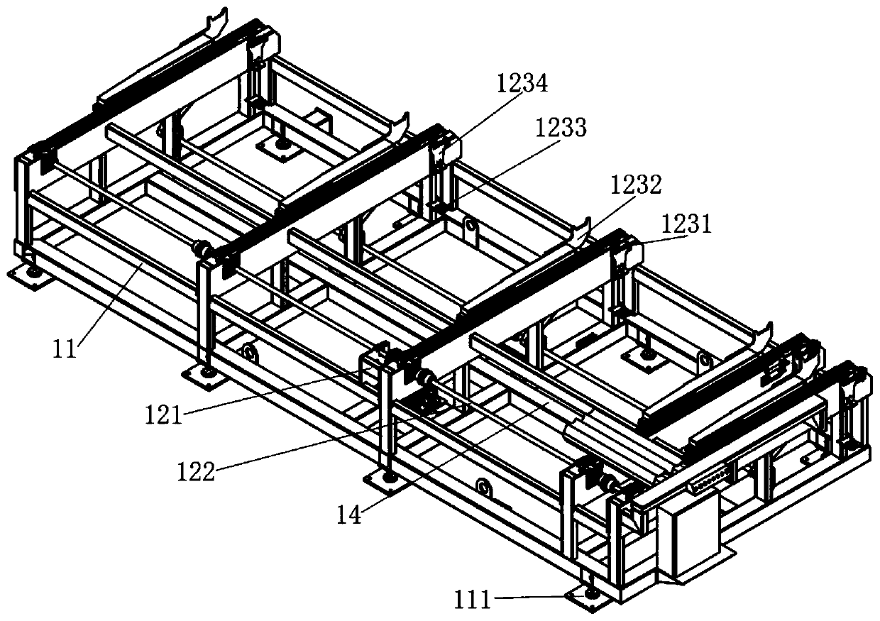
[0034] Such as Figure 1-3 As shown, an automatic loading and unloading device for a pipe cutting machine includes an automatic feeding mechanism 1, a laser pipe cutting machine 2, an automatic blanking device 3 and a workbench 4, and the automatic feeding mechanism 1 is arranged on the workbench 4 side, the laser tube cutting machine 2 is set at the end of the workbench 4, and the automatic blanking device 3 is set at the end of the laser tube cutting machine 2. The automatic feeding mechanism 1 includes a first frame 11, a feeding mechanism 12 and a code material mechanism 13, the bottom of the first frame 11 is provided with a support plate 111, and the first frame 11 is provided with a partition 14. The partition 14 divides the inside of the first frame 11 into two accommodating chambers, the accommodating chambers include a first accommodating chamber 15 and a second accommodating chamber 16, and the first accommodating chamber 15 To be close to the end of the laser pipe...

Embodiment 2

[0039] A working method for an automatic loading and unloading device for a pipe cutting machine, using the automatic loading and unloading device for a pipe cutting machine as described in Embodiment 1 to cut pipes, comprising the following steps:

[0040] (1) Put the pipe to be cut on the buckle 125 of the chain conveyor belt 1231, turn on the second motor 131, the second motor 131 drives the second rotating shaft 132 to rotate, the chain conveyor 1231 is driven by the second rotating shaft 132, and transfers the pipe to On the vertical mechanical transport claw 1234;

[0041] (2) The vertical mechanical delivery claw cylinder 1233 receives the signal, stretches upwards, pushes the pipe to a certain height, the first motor 121 starts after receiving the signal, and the first rotating shaft 122 follows the first motor 121 to rotate, and the first rotating shaft 122 The horizontal mechanical conveying claw 1232 connected by the transmission belt 124 is driven by the first rota...

Embodiment 3

[0046] This embodiment is a modification example of Embodiment 1, on the basis of Embodiment 1, a welding seam identification device 5 is added, such as Figure 5-6 As shown, the welding seam identification device includes a mounting bracket 51 , a connecting part 52 and a rotating part 53 , the connecting part 52 includes a connecting block 521 and a rotating cylinder 522 , and the rotating cylinder 522 is arranged in the connecting block 521 . The rotating part 53 includes a rotating arm 531, the angle between the plane where the rotating arm 531 is located and the plane where the connecting block 521 is located is 45°, one end of the rotating arm 531 is connected with the rotating cylinder 522, and the rotating arm The other end of 531 is provided with a line laser source 533, and a camera 532 is provided near the end of the rotating cylinder 522 on the rotating arm 531. The camera 532 is a GigE area array industrial camera, and the camera 532 and the line laser source 533 a...


PUM


Abstract

The invention discloses an automatic feeding and discharging device for a pipe cutting machine and a working method thereof, and belongs to the field of pipe cutting equipment. The automatic feeding and discharging device for the pipe cutting machine comprises an automatic feeding mechanism, a laser pipe cutting machine, an automatic falling device and a workbench, the automatic feeding mechanismis arranged on the side face of the workbench, the laser pipe cutting machine is arranged at the end of the workbench, the automatic falling device is arranged at the end of the laser pipe cutting machine, the automatic feeding mechanism is used for conveying pipes to the laser pipe cutting machine for cutting, and after cutting is completed, cut finished products are received by the automatic falling device and conveyed to a collecting position. The automatic feeding and discharging device for the pipe cutting machine is suitable for cutting the pipes with various shapes, the structure is simple, the stability is good, electric energy consumption is low, the production cost is low, cutting errors are reduced, the working efficiency is effectively improved, environmental pollution can be effectively reduced, and the product quality is improved. The automatic feeding and discharging device for the pipe cutting machine is simple in working method and suitable for industrial large-scale promotion.

Description

technical field [0001] The invention belongs to the field of pipe cutting equipment, and in particular relates to an automatic loading and unloading device for a pipe cutting machine and a working method thereof. Background technique [0002] With the rapid development of industry, the efficiency and precision of wire cutting and flame cutting can no longer meet the needs of customers, and customers have put forward high requirements for the stability and efficiency of machine tools. Here we have carried out various researches on the laser pipe cutting machine, and added a semi-automatic feeding mechanism and a fully automatic blanking device to the laser pipe cutting machine. [0003] The common automatic feeding mechanism uses a cloth belt to load the workpiece for stacking, and then a variety of motors cooperate with each other to control the retrieving arm to take the material. However, this kind of feeding mechanism has a complex structure, many motion tracks, and poor ...

Claims


Application Information

Patent Timeline
Patent Type & Authority Applications(China)
IPC IPC(8): B23K26/38B23K26/70B23K101/06
CPCB23K26/38B23K26/702B23K2101/06
Inventor 初兴业黄兴义黄传鑫陈明肖俊清
Owner 苏州松谷智能装备股份有限公司
Why Eureka
Try Eureka