Automatic sawing and end milling equipment
A technology of end milling and equipment, applied in the field of hydraulic mold equipment, can solve the problems of low degree of automation, low efficiency, troublesome processing, etc., and achieve the effect of improving efficiency
- Summary
- Abstract
- Description
- Claims
- Application Information
AI Technical Summary
Problems solved by technology
Method used
Image
Examples
Embodiment 1
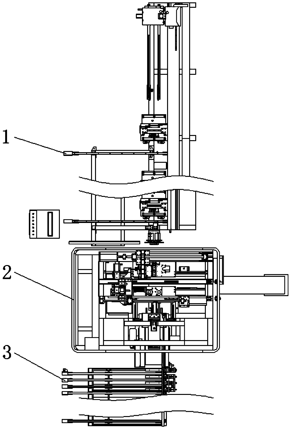
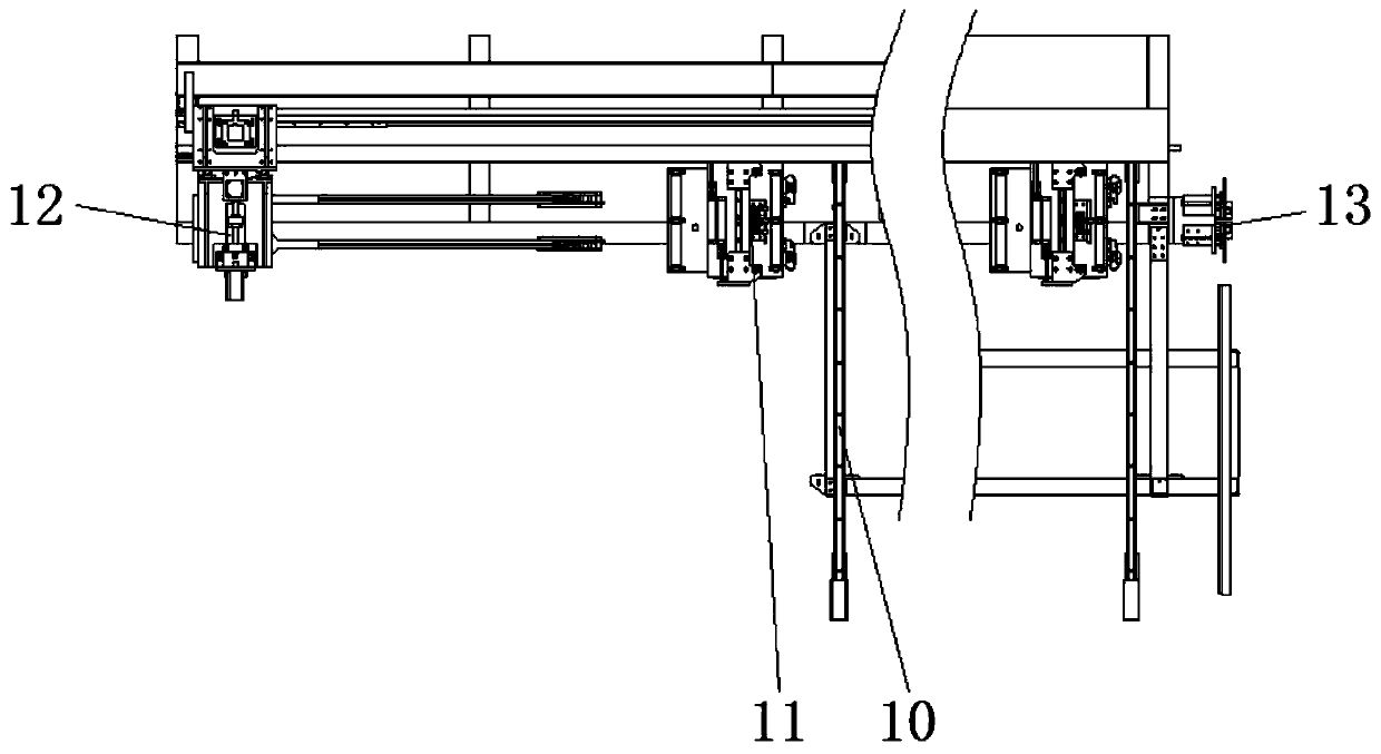
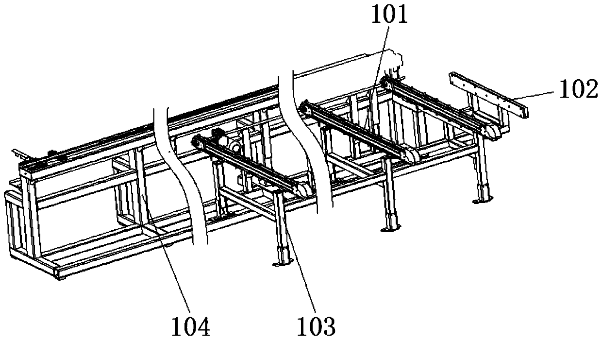
[0042] see Figure 1-6 and Figure 15-17 , an automatic cutting and end milling equipment, including a feeding area 1, a processing area 2 and a material discharging area 3, the feeding area 1 includes a feeding table 10, a profile clamping device 11, a feeding manipulator 12 and a positioning device 13, The loading table 10 includes a synchronous belt turntable A101, a profile baffle plate 102, a feeding base 103 and a feeding frame 104, which are used for transportation. The feeding base 103 is assembled by aluminum profiles and connectors, and the feeding base 103 One side of the base is welded with the profile baffle 102, the preliminary positioning is realized through the profile baffle 102, and the profile is automatically transported to the clamping position by using the synchronous belt turntable A101, and the other side of the feeding base 103 is fixed with the feeding frame 104 through the feet A1 Welding, the bottom of the timing belt turntable A101 is fixedly conn...
Embodiment 2
[0045] Based on Example 1, such as Figure 7-14 , the processing area 2 includes a fixed worktable 20, a mobile worktable 21, a sawing part 22, an end milling part 23, a cutting part 24, a chip removal device 25, a feeding device 26, a label printing device 27 and a mobile operation box 28. The fixed work The base 201 is fixedly installed on the bottom of the table 20. The fixed workbench 20 includes a cylinder B1 and a roller B1202. The lower end of B1202 is provided with a guide shaft B1 and a linear bearing B1, and a roller B2203 is fixedly installed in the vertical direction of the fixed workbench 20. The number of rollers B2203 is two, and the two rollers B2203 are symmetrically distributed. It also includes a horizontal workbench B1204 and a vertical workbench B1205. The horizontal and vertical directions of the fixed workbench 20 are respectively fixedly installed with a horizontal clamp B1206 and a vertical clamp B1207, and one side of the horizontal clamp B1206 is fix...
PUM
 Abstract
Description
Claims
Application Information
 - R&D
- Intellectual Property
- Life Sciences
- Materials
- Tech Scout
- Unparalleled Data Quality
- Higher Quality Content
- 60% Fewer Hallucinations
Browse by: Latest US Patents, China's latest patents, Technical Efficacy Thesaurus, Application Domain, Technology Topic, Popular Technical Reports.
© 2025 PatSnap. All rights reserved.Legal|Privacy policy|Modern Slavery Act Transparency Statement|Sitemap|About US| Contact US: help@patsnap.com


