
Metal cutting fluid recovery processing system

A metal cutting fluid, recovery and treatment technology, applied in fixed filter element filter, filtration separation, solid separation, etc., can solve the problems of affecting the filtering effect, breaking, increasing costs, etc., to improve the filtration cleanliness and recovery rate, The effect of saving filtration cost and increasing cost

Inactive Publication Date: 2020-04-21
张汀仁
View PDF0 Cites 2 Cited by
  • Summary
  • Abstract
  • Description
  • Claims
  • Application Information

AI Technical Summary

Problems solved by technology

[0003] However, the following problems exist in the current recycling of metal cutting fluid filtration. First, most of the existing filtration methods use filter paper to filter the recovered metal cutting fluid. As the filtration progresses, impurities continue to accumulate on the filter paper, which is easy to cause The filter paper is clogged, which affects the filtering effect. The continuous increase of the weight on the filter paper will easily lead to the sinking or rupture of the filter paper, so that the filtered impurities enter the recovery box, resulting in filtration failure, and the filter paper is a consumable, which increases the recovered metal cutting fluid. The cost of filtration; 2. The recovery rate of metal cutting fluid recovery equipment currently on the market is low, and the recovery cleanliness is not enough. It can better filter the recycled metal cutting fluid, improve the filtration cleanliness and recovery of recovered metal cutting fluid Rate

Method used


Image

  • Metal cutting fluid recovery processing system
  • Metal cutting fluid recovery processing system
  • Metal cutting fluid recovery processing system

Examples


Embodiment Construction

[0027] The embodiments of the present invention will be described in detail below with reference to the accompanying drawings, but the present invention can be implemented in many different ways defined and covered by the claims.

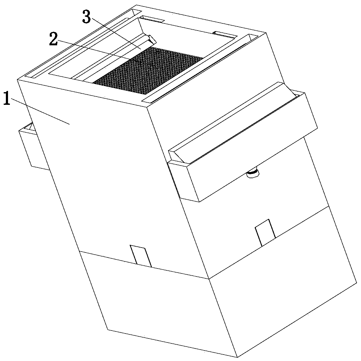
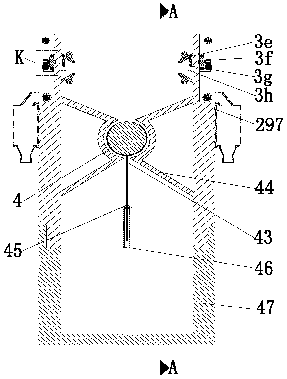
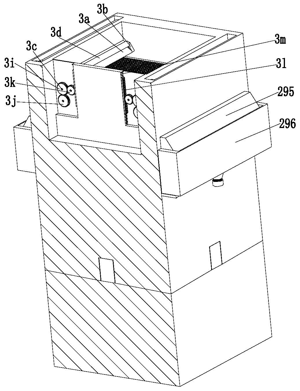
[0028] Such as Figure 1 to Figure 7 As shown, a metal cutting fluid recovery and processing system includes a hollow rectangular tube 1, a primary filter device 2, a closing device 3 and a secondary filter device 4, the upper end of the hollow rectangular tube 1 is equipped with a primary filter device 2, a A tightening device 3 is installed on the primary filtering device 2, and a secondary filtering device 4 is installed at the lower end of the hollow rectangular tube 1.

[0029]Described primary filtering device 2 comprises No. 1 motor 21, filter screen 22, winding roller 23, driven roller 24, projection 25, No. 1 gear 26, rotating rod 27 and hairbrush 28, described hollow rectangle The left and right ends of the upper part of the tube 1 are sy...


PUM


Abstract

The invention relates to a metal cutting fluid recovery processing system. The system comprises a hollow rectangular pipe, a first-stage filtering device, a closing device and a second-stage filteringdevice. The first-stage filtering device is mounted at an upper end of the hollow rectangular pipe; the closing device is mounted on the first-stage filtering device; and the second-stage filtering device is mounted at a lower end of the hollow rectangular pipe. During filtering of a recycled metal cutting fluid, there are the following problems that firstly, in most of existing filtering modes,filter paper is used to filter the recycled metal cutting fluid; as the filtering goes on, impurities are continuously accumulated on the filter paper, the filter paper is easily blocked, a filteringeffect is influenced, weight of the filter paper is continuously increased, and the filter paper easily sinks or cracks so that the filtered impurities enter a recycling box, and filtering failure iscaused; and secondly, metal cutting fluid recovery equipment on a market at present is low in recovery rate and insufficient in recovery cleanliness, and the recovered metal cutting fluid cannot be filtered well. The system of the invention can solve the above problems.

Description

technical field [0001] The invention relates to the technical field of cutting fluid recovery, in particular to a metal cutting fluid recovery and treatment system. Background technique [0002] Metal cutting fluid is an industrial liquid used in metal cutting and grinding to cool and lubricate cutting tools and workpieces. The friction between the rake face and the chip, the flank face and the machined surface forms a part of the lubricating film, thereby reducing the cutting force, friction and power consumption, reducing the surface temperature and tool wear of the friction part between the tool and the workpiece blank, and improving the workpiece material Excellent cutting performance, the metal cutting fluid takes the cutting heat away from the tool and the workpiece through convection and vaporization between it and the tool (or grinding wheel) heated by cutting, chips and workpiece, thereby effectively reducing the cutting temperature. Reduce the thermal deformation ...

Claims


Application Information

Patent Timeline
IPC IPC(8): B03C1/30B01D29/01B01D29/64C10M175/00C10N40/22
CPCB01D29/01B01D29/6415B03C1/30C10M175/00C10M175/0066
Inventor 张汀仁范文祥
Owner 张汀仁
Learn More