
Vacuum electron beam welding method for chromium bronze butt joint of annular workpiece of sandwich structure

A technology of vacuum electron beam and butt joints, which is applied in the direction of electron beam welding equipment, welding equipment, welding equipment, etc., can solve the problems of reducing production efficiency, reducing the bearing capacity of welded parts, and increasing production costs, so as to improve the effective thickness and The effect of bearing capacity, reducing the number of rework welding, and reducing production costs

Active Publication Date: 2020-04-21
XIAN SPACE ENGINE CO LTD
View PDF6 Cites 2 Cited by
  • Summary
  • Abstract
  • Description
  • Claims
  • Application Information

AI Technical Summary

Problems solved by technology

[0002] The back of the direct electron beam welding of the chromium bronze butt joint of the circular workpiece is prone to depression, which reduces the effective wall thickness of the weld and reduces the bearing capacity of the weld
At the same time, the X-ray inspection of chrome bronze electron beam welds is prone to produce pores, which can easily exceed the requirements of electron beam welding standards, resulting in the frequent need for electron beam repair welding to ensure that the internal quality of the weld is qualified
Rework welding reduces production efficiency and increases production costs

Method used

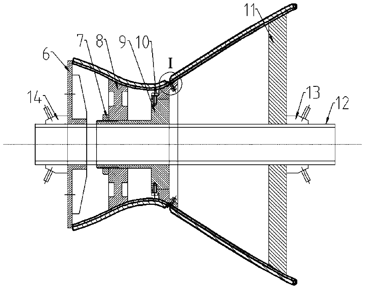
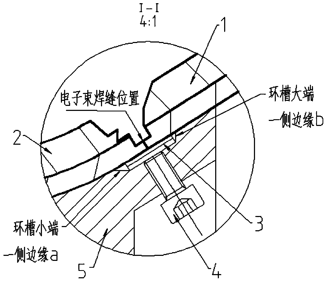
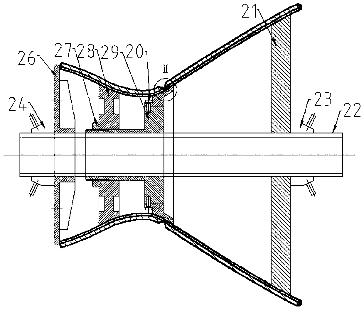

Image

  • Vacuum electron beam welding method for chromium bronze butt joint of annular workpiece of sandwich structure
  • Vacuum electron beam welding method for chromium bronze butt joint of annular workpiece of sandwich structure
  • Vacuum electron beam welding method for chromium bronze butt joint of annular workpiece of sandwich structure

Examples


Embodiment 1

[0053] (1) Workpieces A and B are brazed rings with a sandwich structure whose outer wall is stainless steel and whose inner wall is chrome bronze. The inner wall thickness of the chrome bronze of workpiece A and workpiece B is 1.2mm, the material grade is QCr0.8, and the weld diameter is φ260mm. Use blade scraping to clean the chrome-bronze joint surfaces of workpiece A and workpiece B to expose the metallic luster, and perform welding within 24 hours.

[0054] (2) Positioning pieces A and B are positioned on the outer wall by manual argon arc welding, and the distance between adjacent positioning pieces is 180mm. The misalignment of the back of the chrome bronze butt weld after the positioning of workpiece A and workpiece B is 0.1mm, and the gap is 0.1mm. The material of the copper backing plate clamped on the back of the weld is consistent with the inner wall of the workpiece, the width is 12mm, and the thickness of each layer is 1mm. After overlapping the two layers of co...

Embodiment 2

[0059] (1) Workpieces A and B are brazed rings with a sandwich structure whose outer wall is stainless steel and whose inner wall is chrome bronze. The chrome bronze inner wall thickness of workpiece A and workpiece B is 2mm, the material grade is QCr0.8, and the weld seam diameter is φ120mm. Use blade scraping to clean the chrome-bronze joint surfaces of workpiece A and workpiece B to expose the metallic luster, and perform welding within 24 hours.

[0060] (2) Use positioning pieces to position A workpiece and B workpiece by manual argon arc welding on the outer wall, and the distance between adjacent positioning pieces is 150mm. The misalignment of the back of the chrome bronze butt weld after the positioning of workpiece A and workpiece B is 0.05mm, and the gap is 0.05mm. The material of the copper backing plate clamped on the back of the weld is consistent with the inner wall of the workpiece, the width is 10mm, and the thickness of each layer is 1mm. After overlapping t...

Embodiment 3

[0065] (1) Workpieces A and B are brazed rings with a sandwich structure whose outer wall is stainless steel and whose inner wall is chrome bronze. The chrome bronze inner wall thickness of workpiece A and workpiece B is 3mm, the material grade is QCr0.8, and the weld seam diameter is φ800mm. Use blade scraping to clean the chrome-bronze joint surfaces of workpiece A and workpiece B to expose the metallic luster, and perform welding within 24 hours.

[0066](2) Positioning pieces A and B are positioned on the outer wall by manual argon arc welding, and the distance between adjacent positioning pieces is 200mm. The misalignment of the back of the chrome bronze butt weld after the positioning of workpiece A and workpiece B is 0.1mm, and the gap is 0.1mm. The material of the copper backing plate clamped on the back of the weld is consistent with the inner wall of the workpiece, the width is 14mm, and the thickness of each layer is 1mm. After overlapping the two layers of copper ...


PUM

PropertyMeasurementUnit
Widthaaaaaaaaaa

Abstract

The invention provides a vacuum electron beam welding method for a chromium bronze butt joint of an annular workpiece of a sandwich structure. The vacuum electron beam welding method comprises the following steps of clamping the workpiece by adopting a first clamping tool; enabling a copper base plate to be tightly attached to the back surface of a weld joint of the workpiece; after electron beamsegmented positioning welding is carried out, disassembling the workpiece and the first clamping tool, correcting the copper base plate on the back surface of the weld joint, and enabling the back surface of the weld joint to be tightly attached to the copper base plate; and clamping the workpiece by using a second clamping tool for formal welding, allowing the chromium bronze butt joint weld joint of the workpiece and the copper base plate to be completely welded by the second clamping tool, and removing the copper base plate on the back surface of the weld joint of the workpiece by adoptinga manual grinding mode after welding. According to the vacuum electron beam welding method, the problem that the back surface of the chromium bronze electron beam weld joint is prone to generating pits is solved, meanwhile, the probability that air holes appear in the chromium bronze electron beam weld joint is obviously reduced, so that the first-pass yield of X-ray inspection of the workpiece isremarkably improved, the number of times of repair welding of the workpiece is reduced, and the production cost is reduced.

Description

technical field [0001] The invention relates to a method for vacuum electron beam welding of chromium bronze, in particular to a method for vacuum electron beam welding of chromium bronze butt joints of annular workpieces with a sandwich structure, and belongs to the field of mechanical processing. Background technique [0002] The back of the weld of the direct electron beam welding of the chrome bronze butt joint of the circular workpiece is prone to depression, which reduces the effective wall thickness of the weld and reduces the bearing capacity of the weld. At the same time, the X-ray inspection of chrome bronze electron beam welds is prone to produce pores, which can easily exceed the requirements of electron beam welding standards, resulting in the frequent need for electron beam repair welding to ensure that the internal quality of the weld is qualified. Rework welding reduces production efficiency and increases production costs. Contents of the invention [0003...

Claims


Application Information

Patent Timeline
IPC IPC(8): B23K15/04B23K37/00B23K37/04B23K103/12
CPCB23K15/04B23K37/00B23K37/0435B23K2103/12
Inventor 杨卫鹏薄佑锋王英杰
Owner XIAN SPACE ENGINE CO LTD
Learn More