Hollow shaft and manufacturing method thereof
A manufacturing method and hollow shaft technology, applied in the directions of shafts, bearings, shafts and bearings, can solve the problems of large processing volume, waste of raw materials, parts failure, etc., to reduce deformation resistance, improve appearance quality, and prevent metal from being corroded. Effect
- Summary
- Abstract
- Description
- Claims
- Application Information
AI Technical Summary
Problems solved by technology
Method used
Image
Examples
Embodiment 1
[0049] In the traditional hollow shaft processing technology, the amount of machining is large, and raw materials are wasted, and defects are prone to occur at the welds, causing premature failure of parts. Compared with solid shafts, it is more difficult to process hollow shafts with necking at both ends. Therefore, the present invention provides a hollow shaft and its manufacturing method to solve the above problems.
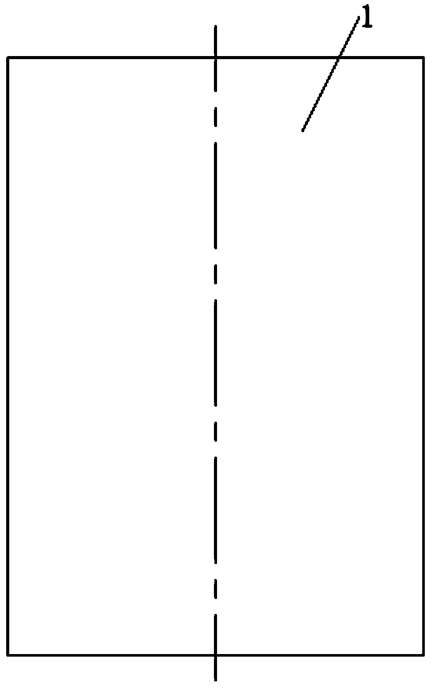
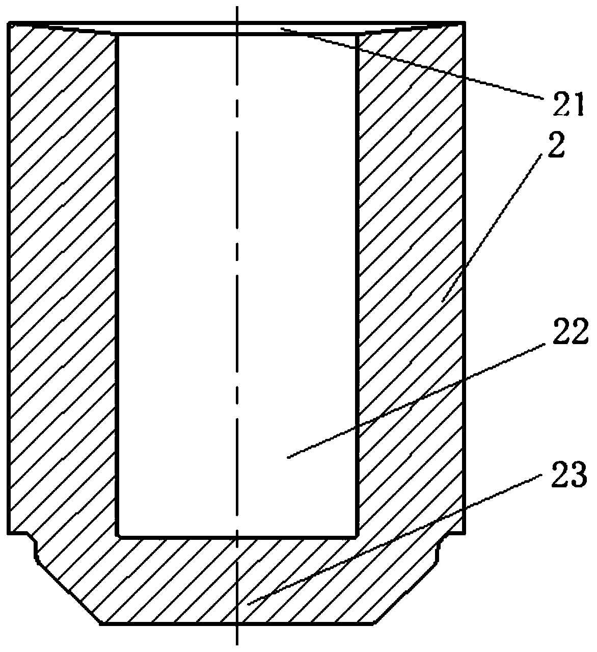
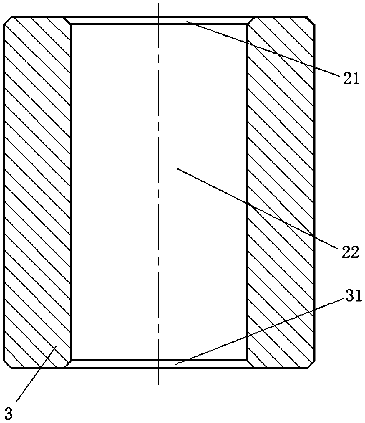
[0050] figure 1 It is a structural schematic diagram of the bar stock described in the present invention; figure 2 It is a schematic cross-sectional view of the blank described in the present invention; image 3 It is a schematic cross-sectional view of the tubular rough blank of the present invention; Figure 4 It is a schematic cross-sectional view of the tubular thin billet of the present invention; Figure 5 It is a schematic cross-sectional view of the tubular compact according to the present invention; Image 6 It is a structural schematic view of t...
Embodiment 2
[0082] In the traditional hollow shaft processing technology, the amount of machining is large, and raw materials are wasted, and defects are prone to occur at the welds, causing premature failure of parts. Compared with solid shafts, it is more difficult to process hollow shafts with necking at both ends. Therefore, the present invention provides a hollow shaft and its manufacturing method to solve the above problems.
[0083] figure 1 It is a structural schematic diagram of the bar stock described in the present invention; figure 2 It is a schematic cross-sectional view of the blank described in the present invention; image 3 It is a schematic cross-sectional view of the tubular rough blank of the present invention; Figure 4 It is a schematic cross-sectional view of the tubular thin billet of the present invention; Figure 5 It is a schematic cross-sectional view of the tubular compact according to the present invention; Image 6 It is a structural schematic view of t...
Embodiment 3
[0115] In the traditional hollow shaft processing technology, the amount of machining is large, and raw materials are wasted, and defects are prone to occur at the welds, causing premature failure of parts. Compared with solid shafts, it is more difficult to process hollow shafts with necking at both ends. Therefore, the present invention provides a hollow shaft and its manufacturing method to solve the above problems.
[0116] figure 1 It is a structural schematic diagram of the bar stock described in the present invention; figure 2 It is a schematic cross-sectional view of the blank described in the present invention; image 3 It is a schematic cross-sectional view of the tubular rough blank of the present invention; Figure 4 It is a schematic cross-sectional view of the tubular thin billet of the present invention; Figure 5 It is a schematic cross-sectional view of the tubular compact according to the present invention; Image 6 It is a structural schematic view of t...
PUM
 Abstract
Description
Claims
Application Information
 - R&D
- Intellectual Property
- Life Sciences
- Materials
- Tech Scout
- Unparalleled Data Quality
- Higher Quality Content
- 60% Fewer Hallucinations
Browse by: Latest US Patents, China's latest patents, Technical Efficacy Thesaurus, Application Domain, Technology Topic, Popular Technical Reports.
© 2025 PatSnap. All rights reserved.Legal|Privacy policy|Modern Slavery Act Transparency Statement|Sitemap|About US| Contact US: help@patsnap.com


