Medium-temperature sub-high pressure reheating waste incineration boiler provided with sound wave temperature measurement denitration system

A waste incineration, sub-high pressure technology, applied in steam boilers, superheated temperature control, combustion methods, etc., can solve the problems of inability to adjust reheat steam temperature, large difference in superheated steam temperature, and large amount of urea or ammonia water. The effect of increasing the steam working capacity, reducing the height of the boiler, and reducing the dosage of chemicals

Pending Publication Date: 2020-04-21
ZHEJIANG WEIMING ENVIRONMENT PROTECTION
View PDF0 Cites 0 Cited by
  • Summary
  • Abstract
  • Description
  • Claims
  • Application Information

AI Technical Summary

Problems solved by technology

In addition, with the improvement of environmental protection requirements, the traditional SNCR technology has large load fluctuations due to unstable working conditions, large fluctuations in denitrification efficiency, and excessive use of urea or ammonia water. Excessive reducing agents are likely to cause increased denitrification costs and increased ammonia slip. , water wall corrosion and a series of problems
In addition, the temperature of the reheated steam in the existing equipment cannot be adjusted, resulting in a large temperature difference with the superheated steam, which affects the operation of the low-pressure cylinder

Method used


Image

  • Medium-temperature sub-high pressure reheating waste incineration boiler provided with sound wave temperature measurement denitration system
  • Medium-temperature sub-high pressure reheating waste incineration boiler provided with sound wave temperature measurement denitration system
  • Medium-temperature sub-high pressure reheating waste incineration boiler provided with sound wave temperature measurement denitration system

Examples


Embodiment Construction

[0026] The present invention will be further described below in conjunction with the accompanying drawings.

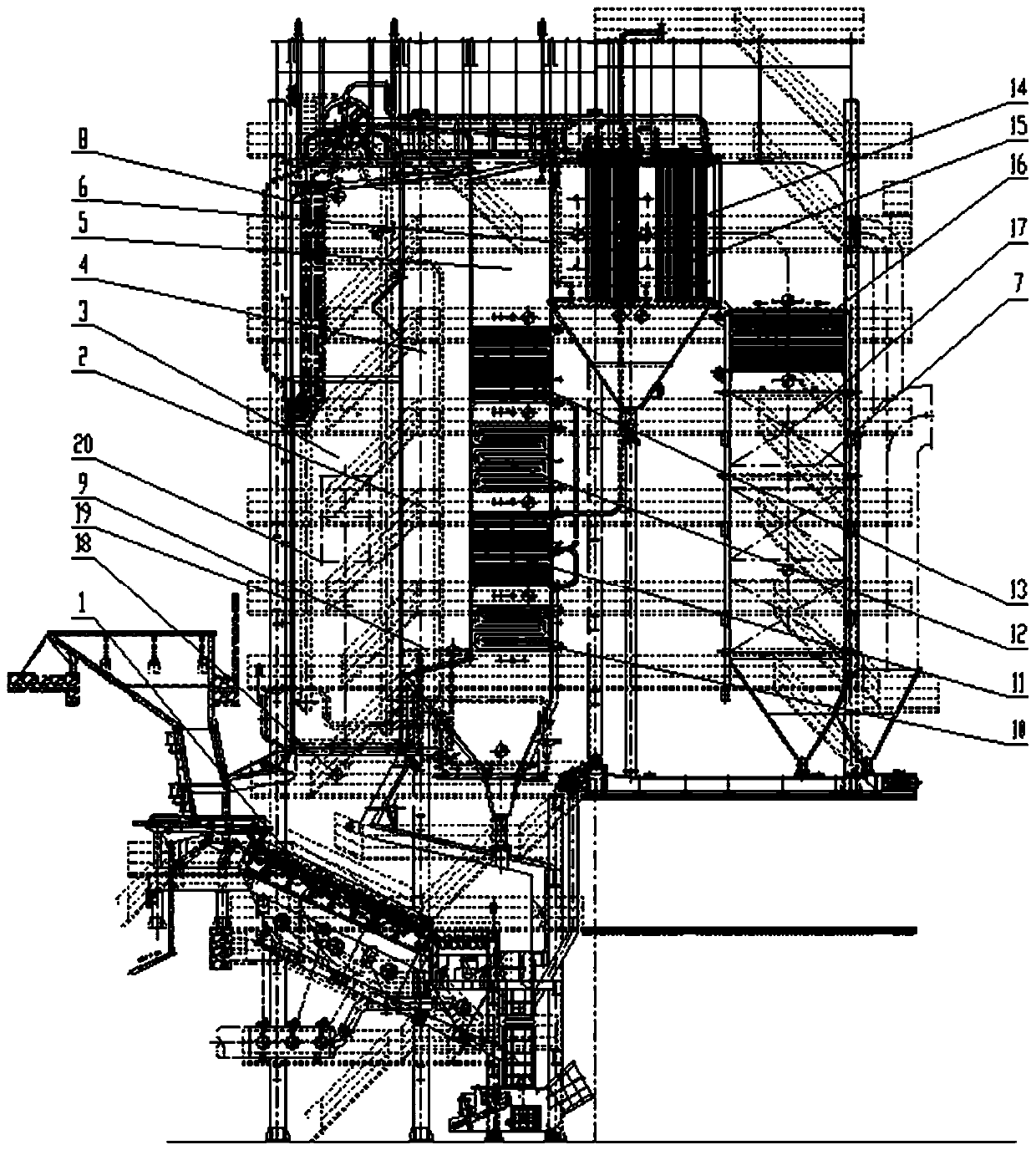
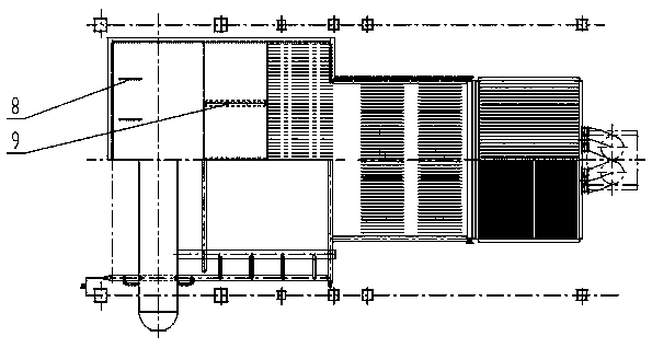
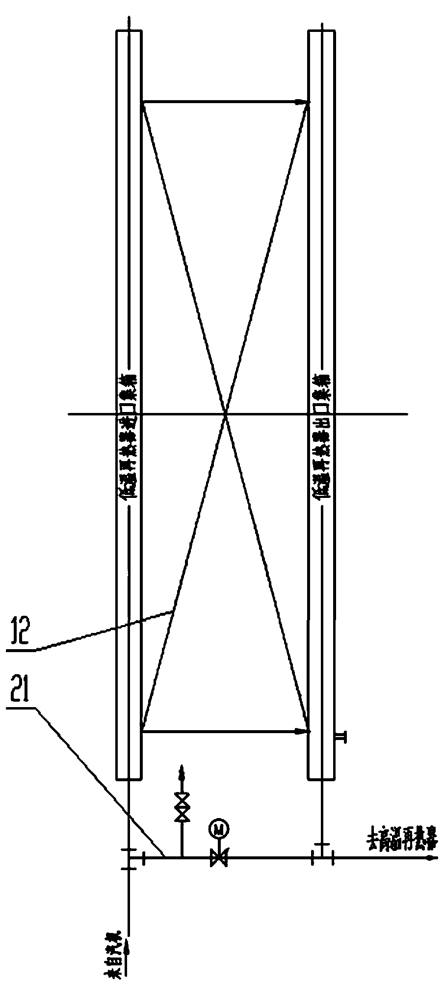
[0027] Such as figure 1 As shown, the medium-temperature sub-high pressure reheating waste incineration boiler equipped with an acoustic temperature measurement and denitrification system of the present invention includes a grate 1, a furnace chamber 2, a horizontal flue 6 and a tail flue 7. The furnace chamber 2 includes a furnace chamber 3, an ember chamber 4 and three flues 5 connected in sequence; a horizontal flue 6 and a tail flue 7 are sequentially arranged behind the furnace chamber 2. The upper part of the furnace 3 is provided with several water-cooled screens 8; the ember chamber 4 is provided with several partition water-cooled walls 9; the three flues 5 are arranged in sequence from bottom to top with high-temperature reheaters 10 and high-temperature superheaters 11. Low-temperature reheater 12, medium-temperature superheater I13; medium-temperature supe...


PUM


Abstract

The invention belongs to the technical field of combustion equipment and particularly relates to a medium-temperature sub-high-pressure reheating waste incineration boiler provided with a sound wave temperature measurement denitration system. The boiler comprises a fire grate, a furnace chamber, a horizontal flue and a tail flue. The furnace chamber comprises a hearth, a burnout chamber and threeflues which are connected in sequence; and the horizontal flue and the tail flue are sequentially arranged behind the furnace chamber. A plurality of water cooling screens are arranged at an upper part of the hearth; a plurality of partition wall water cooling walls are arranged in the burnout chamber; a high-temperature reheater, a high-temperature superheater, a low-temperature reheater and a medium-temperature superheater I are sequentially arranged in the three flues from bottom to top; a medium-temperature superheater II and a low-temperature superheater I are arranged in the horizontal flue; and the tail flue is sequentially provided with a low-temperature superheater II and an economizer from top to bottom. The waste incineration power generation heat efficiency can be effectively improved, the steam consumption rate is reduced, nitrogen oxide emission is efficiently controlled, and long-term safe and stable operation of the water cooling walls, the reheaters and the superheaters is guaranteed.

Description

technical field [0001] The invention belongs to the technical field of combustion equipment, and in particular relates to a medium-temperature sub-high pressure reheating garbage incineration boiler equipped with an acoustic temperature measurement and denitrification system. Background technique [0002] With the acceleration of urbanization in my country, the contradiction between the rapid growth of urban waste and the shortage of land resources has become increasingly apparent. As one of the effective ways to centralize domestic waste, waste incineration has become the best choice for comprehensive waste disposal in large cities. At present, the boiler parameters of waste incineration power plants at home and abroad are generally medium temperature and medium pressure, that is, the steam pressure is 4Mpa, and the steam temperature is 400°C. However, in order to further improve the thermal efficiency of the whole plant for power generation and meet the needs of energy savi...

Claims


Application Information

Patent Timeline
IPC IPC(8): F22B31/08F22G5/12F23J15/04
CPCF22B31/08F22G5/12F23J15/04F23J2215/10
Inventor 李荣刘超黄慧静
Owner ZHEJIANG WEIMING ENVIRONMENT PROTECTION
Why Eureka
Try Eureka