Threaded nut of ball screw drive

A technology of ball screw and transmission device, which is applied in the direction of transmission device, gear transmission device, brake, etc., to achieve the effect of small size and uniform property characteristics

Inactive Publication Date: 2020-04-21
SCHAEFFLER TECH AG & CO KG
View PDF4 Cites 0 Cited by
  • Summary
  • Abstract
  • Description
  • Claims
  • Application Information

AI Technical Summary

Problems solved by technology

In special applications such as in spindle bearings rotating at high speeds, the metal / metal rolling contact in the contact track area disadvantageously produces higher wear compared to conventional applications

Method used


Image

  • Threaded nut of ball screw drive
  • Threaded nut of ball screw drive
  • Threaded nut of ball screw drive

Examples


Embodiment Construction

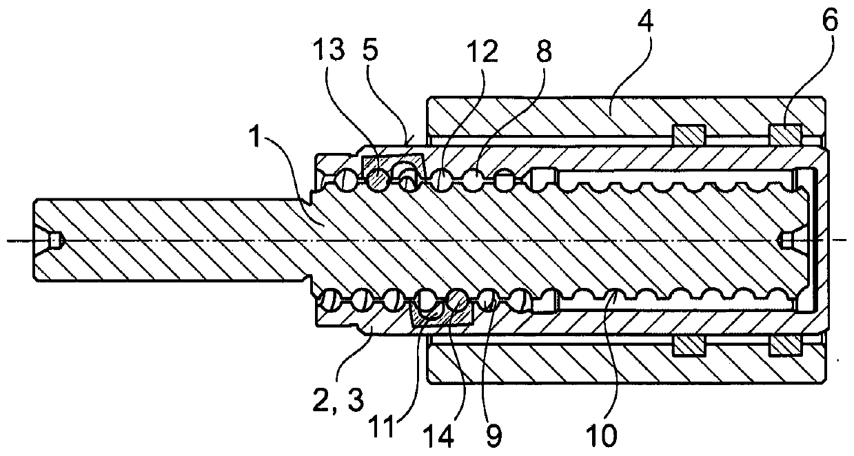
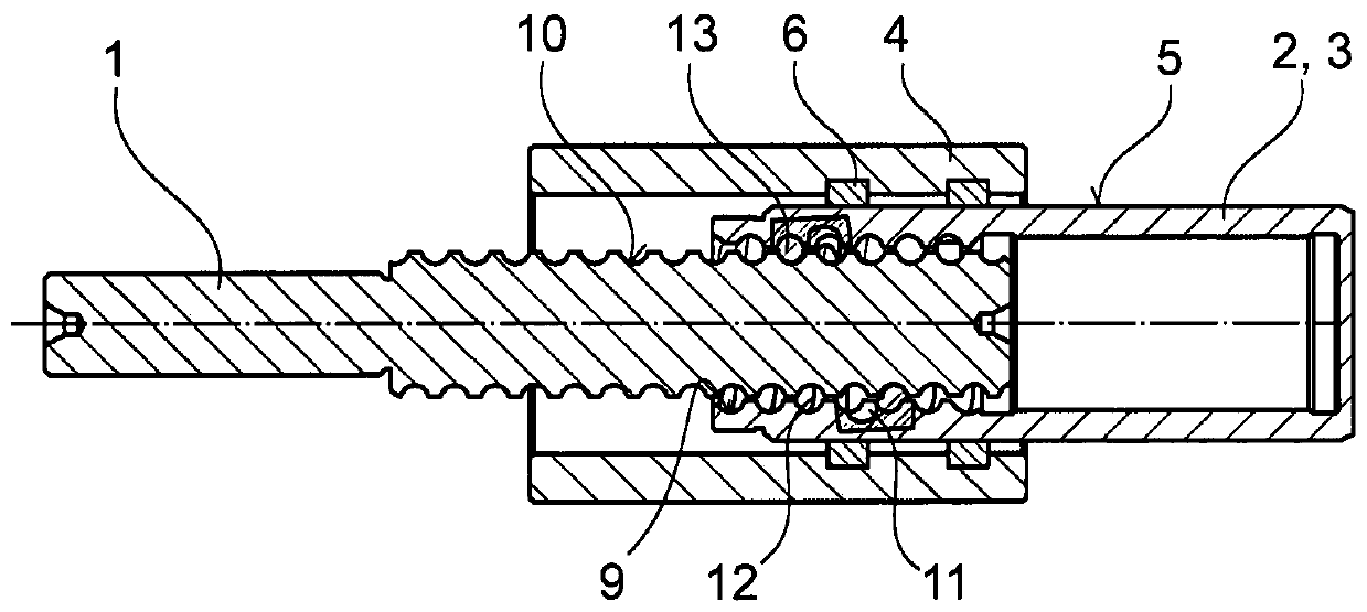
[0031] figure 1 with figure 2 A first embodiment of the ball screw transmission device according to the present invention is shown. The ball screw transmission device has a screw 1 driven in rotation and a nut 2 arranged on the screw 1 to be movable in the axial direction. figure 1 Shows a ball screw drive with a nut 2 that has been moved in and figure 2 The ball screw drive with the nut 2 pulled out is shown.

[0032] The nut 2 is configured as a piston 3 which engages in a cylinder 4 which is only schematically shown. Instead of the cylinder ground, a housing may also be provided. The outer peripheral surface of the nut 2 is configured as a cylindrical sealing surface 5 of the piston 3. The hydraulic pressure chamber defined by the piston 3 and the cylinder 4 is not shown. The pressure chamber is connected to the right end of the cylinder 4. When the ball screw drive is operated (that is, when the screw 1 is driven in rotation), the piston 3 is displaced relative to the cyl...


PUM


Abstract

The invention relates to a threaded nut (2) of a ball screw drive, having a ball groove (9) which is formed on the internal periphery and is wound helically around a spindle axis of the ball screw drive, the threaded nut (2) being formed as a hydraulic piston (3) from a martensitically hardened steel which is corrosion-resistant with respect to brake fluid and which contains, expressed in percentages by weight: at least 0.4% and up to 1.3% carbon C, and up to 2% silicon Si, and up to 2% manganese Mn, and at least 12% and up to 20% chromium Cr, as well as 0% and up to 2% molybdenum Mo, and 0% and up to 0.2% vanadium V, and 0% and up to 3% nickel Ni, and less than 0.015% phosphorus P and sulfur S combined, the remainder being iron.

Description

Technical field [0001] The invention relates to a nut of a ball screw transmission device and a ball screw transmission device. This transmission device converts rotational motion into translational motion. The present invention also relates to an electro-hydraulic brake and a brake force amplifier, in which such a ball screw transmission device is installed to generate hydraulic working pressure. The ball screw drive is preferably operated by an electric motor. Optionally, the nut or screw is driven in rotation. Background technique [0002] Known from DE102012217092 A1 is a brake booster having a ball screw drive according to the preamble of claim 1. The nut of the ball screw drive is implemented as a piston, and the outer peripheral surface of the piston is configured as a cylindrical outer sealing surface. As a piston element, the nut must also assume a sealing function and must be corrosion resistant against corrosive media such as brake fluid. In addition, the nut as a...

Claims


Application Information

Patent Timeline
Patent Type & Authority Applications(China)
IPC IPC(8): C22C38/02C22C38/04C22C38/18C22C38/22C22C38/24C22C38/40C22C38/38C22C38/44C22C38/46C22C38/58F16H1/00
CPCC22C38/02C22C38/04C22C38/18C22C38/22C22C38/24C22C38/38C22C38/40C22C38/44C22C38/46C22C38/58C21D2211/008F16H2025/2481F16H25/24F16H25/2204B60T13/745F16D2125/40B60T13/10F16D65/14
Inventor 西古德·威廉迪特尔·艾德勒恩斯特·斯特里安
Owner SCHAEFFLER TECH AG & CO KG
Why Eureka
Try Eureka