Multi-spark-plug fuel gas jun porcelain kiln
A kind of kiln and Jun porcelain technology, which is applied in the field of multi-burner gas-fired Jun porcelain kiln, which can solve problems such as unreasonable position of burners, difficult formation of kiln reducing atmosphere, air pollution, etc., to ensure continuity and integrity , Improving the artistic appearance and improving the yield
- Summary
- Abstract
- Description
- Claims
- Application Information
AI Technical Summary
Problems solved by technology
Method used
Image
Examples
Embodiment 1
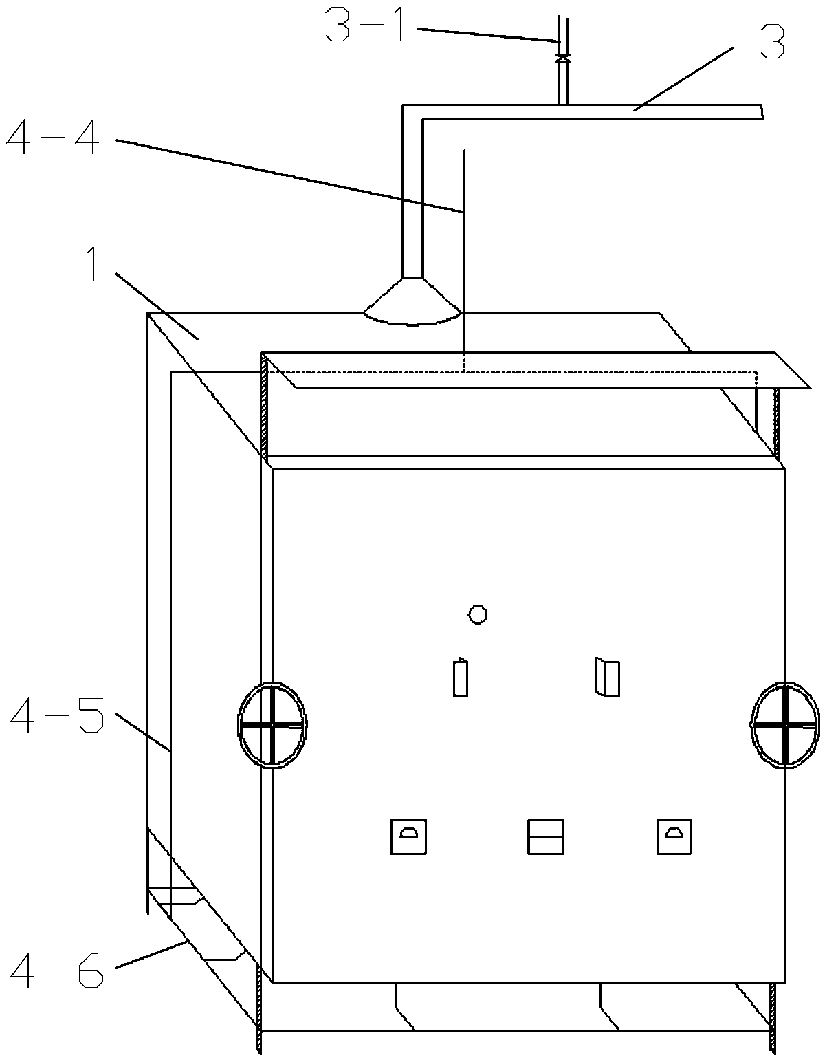
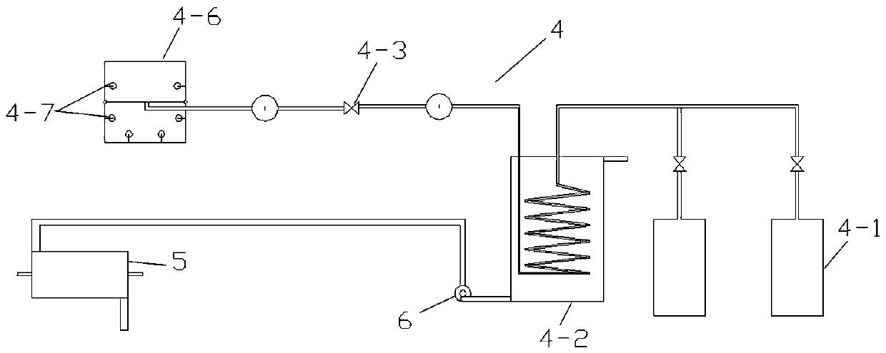
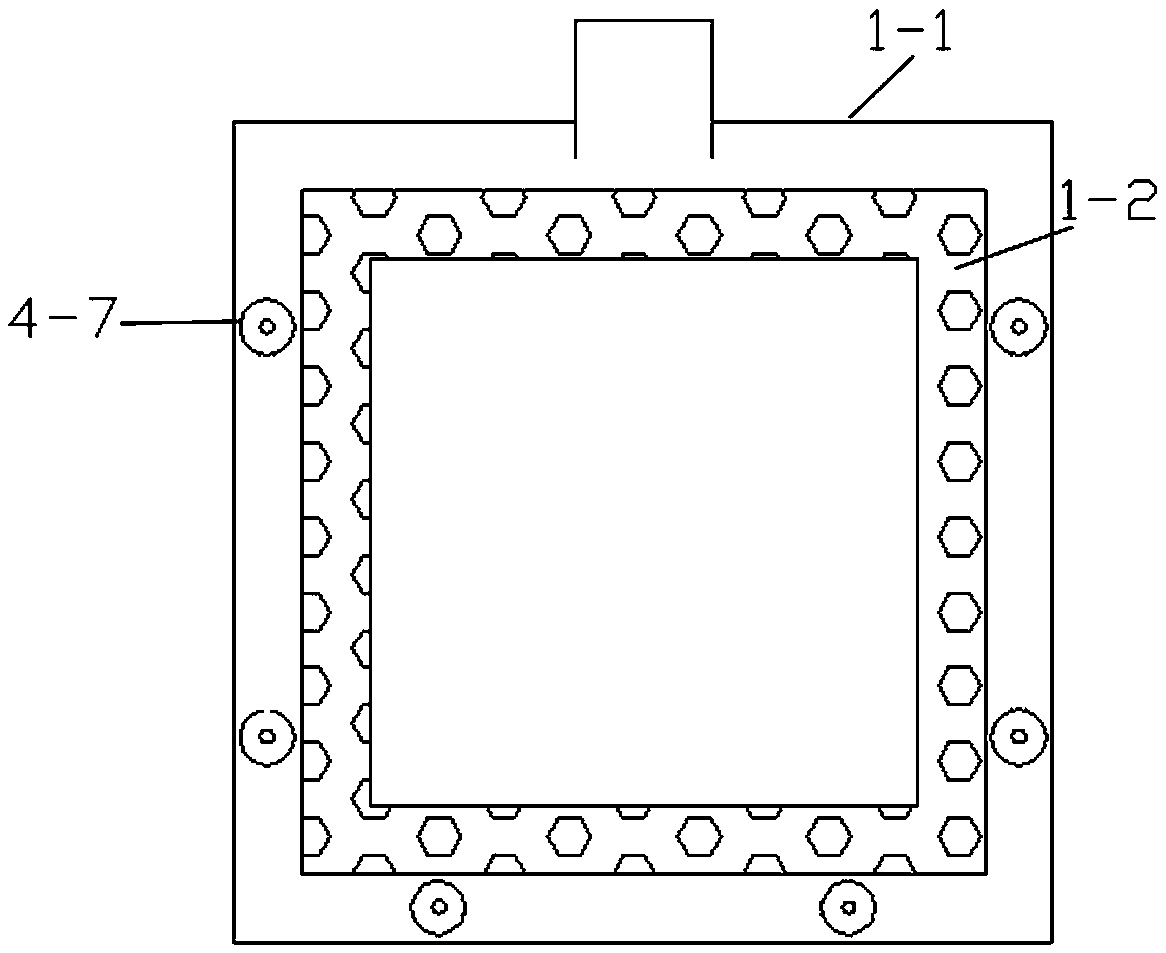
[0026] As shown in the figure: this embodiment provides a multi-burner gas-fired porcelain kiln, which includes a kiln body 1, and the kiln body 1 includes an outer kiln body 1-1 and an inner kiln body 1-2. The kiln body 1-1 and the inner kiln body 1-2 are both cuboid structures, the inner kiln body 1-2 is a hollow structure made of refractory bricks, and the gap between the outer kiln body 1-1 and the inner kiln body 1-2 A mezzanine space for installing the flame nozzle assembly is formed, and the flame nozzle assembly is installed on the front and both sides of the inner kiln body 1-2, and the device can be further installed on the back of the inner kiln body 1-2 as required With flame nozzle assembly. On the back side of the mezzanine space, a smoke exhaust pipe 2 protrudes from the inside to the outside and communicates with the external chimney 3. A fire baffle 7 is arranged at the lower end of the smoke exhaust pipe 2, and the chimney 3 is set on the top of the smoke exh...
Embodiment 2
[0033] As a second embodiment, a smoke exhaust pipe 2 protrudes from the inside to the outside on the back side of the interlayer space and communicates with the external chimney 3. The inside of the chimney 3 is provided with a heating pipe 3-2, and the heating pipe 3-2 One end of the heating pipe 3-2 is connected with the pipeline pump 6, and the pipeline pump 6 is arranged at the liquid outlet of the preheater 4-2, and the other end of the heating pipe 3-2 is connected with the liquid inlet of the preheater 4-2. This kind of setting structure is simpler, and there is no need to install additional devices such as heat exchangers, so the equipment investment is small, but the utilization rate of the equipment for waste heat is low.
Embodiment 3
[0035] In this scheme, a smoke exhaust pipe 2 protrudes from the inside to the outside on the back side of the interlayer space and communicates with the external chimney 3. A jacket can also be provided outside the chimney 3, and the jacket passes through the pipe and the preheater 4 The heating medium in -2 is circulated through the pipeline pump 6 to preheat the gas source. The gas in this scheme is liquefied petroleum gas. Compared with Example 1, this solution does not need to be provided with a bypass heat supply pipe on the chimney 3, and the heating is more direct. This implementation is similar to Example 2, and the waste heat utilization efficiency is low, and the preheater 4-2 The temperature fluctuation of the internal heating medium is relatively large. In this scheme, the heating medium adopts heating oil.
PUM
 Abstract
Description
Claims
Application Information
 - R&D
- Intellectual Property
- Life Sciences
- Materials
- Tech Scout
- Unparalleled Data Quality
- Higher Quality Content
- 60% Fewer Hallucinations
Browse by: Latest US Patents, China's latest patents, Technical Efficacy Thesaurus, Application Domain, Technology Topic, Popular Technical Reports.
© 2025 PatSnap. All rights reserved.Legal|Privacy policy|Modern Slavery Act Transparency Statement|Sitemap|About US| Contact US: help@patsnap.com


