In-situ measurement method based on electron paramagnetic resonance-magnetic resonance imaging three-dimensional magnetic field

A technology of electron paramagnetic resonance and nuclear magnetic resonance, applied in the direction of the magnitude/direction of the magnetic field, stray field compensation, etc., can solve the problems of low measurement sensitivity and precision, and achieve the goal of improving sensitivity and precision, improving precision, and high sensitivity and precision Effect

Active Publication Date: 2020-04-24
BEIJING AUTOMATION CONTROL EQUIP INST
View PDF10 Cites 6 Cited by
  • Summary
  • Abstract
  • Description
  • Claims
  • Application Information

AI Technical Summary

Problems solved by technology

The current three-dimensional magnetic field measurement has low sensitivity and precision, and the magnetic field measurement probe is not in the same position as the atomic gas chamber, and the measured magnetic field is not the residual magnetic field that the nuclear spin actually feels. These two factors limit the improvement of the accuracy of active magnetic compensation.

Method used


Image

  • In-situ measurement method based on electron paramagnetic resonance-magnetic resonance imaging three-dimensional magnetic field
  • In-situ measurement method based on electron paramagnetic resonance-magnetic resonance imaging three-dimensional magnetic field
  • In-situ measurement method based on electron paramagnetic resonance-magnetic resonance imaging three-dimensional magnetic field

Examples


Embodiment Construction

[0029] The present invention will be described in further detail below in conjunction with the accompanying drawings and specific embodiments.

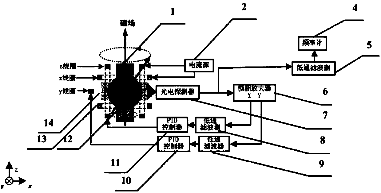
[0030] A method for in-situ measurement of a three-dimensional magnetic field based on electron paramagnetic resonance-nuclear magnetic resonance, comprising the steps of:

[0031] Step 1: Heating

[0032] The atomic gas cell 12 is heated to above 120° C. for increasing the atomic density. The atomic gas chamber 12 contains two kinds of nuclear spins of the inert gas for sensitive magnetic fields and electron spins of the alkali metal atoms, as well as auxiliary function gas atoms N 2 . Among them, the inert gas nuclear spin atoms are two kinds of helium 3, neon 21, krypton 83, xenon 129, xenon 131, in this embodiment, xenon 129 atoms and xenon 131 atoms, alkali metal atoms such as potassium, rubidium, cesium, This embodiment is cesium atom.

[0033] Step Two: Polarization

[0034] A beam of driving laser light 1 is vertically in...


PUM


Abstract

The invention discloses an in-situ measurement method based on an electron paramagnetic resonance-magnetic resonance imaging three-dimensional magnetic field. The in-situ measurement method comprisesthe following steps: step 1, performing heating; step 2, performing polarization; step 3, performing electron paramagnetic resonance and magnetic resonance imaging; and step 4, performing three-dimensional magnetic field in-situ measurement. The method has the following beneficial effects: the measurement sensitivity and precision of the residual magnetic field measurement after passive magnetic shielding in the magnetic resonance imaging gyroscope are improved; a sensitive source of the measured magnetic field and a sensitive source for measuring angular motion are located in the same atomicair chamber and are real magnetic fields with nuclear spin feeling, the active magnetic compensation precision is improved and thus the zero-bias stability of the gyroscope is further improved; meanwhile, an atom magnetometer constructed based on the method can work in a geomagnetic field environment, high sensitivity and precision are realized, and the in-situ measurement method can be applied tothe fields of magnetic anomaly detection, geomagnetic navigation, deep space detection and the like.

Description

technical field [0001] The invention belongs to a magnetic field measurement method, in particular to a three-dimensional magnetic field in-situ measurement method based on electron paramagnetic resonance-nuclear magnetic resonance. Background technique [0002] Based on the cutting-edge research progress of atomic manipulation technology, nuclear magnetic resonance gyroscope has comprehensive advantages such as high precision and small size. It is one of the main development directions of high-precision and micro-miniature gyroscope technology in the future. The NMR gyroscope needs to shield the ambient magnetic field to isolate the influence of the magnetic field on the measurement of nuclear spin precession. Generally, the scheme of "passive magnetic shielding based on high magnetic permeability material + active magnetic compensation based on three-dimensional magnetic field measurement" is adopted. Passive magnetic shielding generally only achieves 10 5 ~10 6 The mag...

Claims


Application Information

Patent Timeline
Patent Type & Authority Applications(China)
IPC IPC(8): G01R33/025
CPCG01R33/025
Inventor 秦杰万双爱孙晓光刘建丰汤恩琼郭宇豪薛帅
Owner BEIJING AUTOMATION CONTROL EQUIP INST
Why Eureka
Try Eureka