Light path light split unit and coaxial wire feed cladding head thereof

A spectroscopic unit and coaxial wire feeding technology, which is applied in the direction of optical components, optics, and condenser mirrors, can solve problems such as cladding defects, optical Louis divergence, and complex structures, so as to reduce energy loss, save water cooling systems, and improve energy distribution. uniform effect

Pending Publication Date: 2020-04-28
HUAZHONG UNIV OF SCI & TECH
View PDF3 Cites 5 Cited by
  • Summary
  • Abstract
  • Description
  • Claims
  • Application Information

AI Technical Summary

Problems solved by technology

[0005] However, most of the existing wire-feed cladding technologies that have been used at present use side-axis wire-feed cladding, which has low processing flexibility and can only be shaped along the wire-feeding direction. Since the laser is focused and conical, the laser effect The molten pool formed on the substrate deviates from the molten drop formed by the laser on the wire in the horizontal direction, which will make it difficult for the molten drop formed by the melting of the wire to drop into the molten pool of the substrate, resulting in overlay defects, which greatly limits the promotion of wire feeding cladding technology
[0006] In order to improve the above-mentioned problems of side-axis wire feeding cladding, Patent Document 1 (publication number: CN 105499793A) discloses an optical path beam splitting unit of a coaxial wire feeding cladding laser head. The collimated beam is divided into four parallel beams, which are incident on the focusing mirror, and the four collimated beams are focused on the wire through the metal inclined plane mirror. This method cannot adjust the final focusing angle of the four beams, which is difficult. Ensure that the focused four beams of light are all focused on the wire, and a large number of optical lenses with complex structures are used in this method, which is difficult to process and high in application cost; The requirements are very high, the thermal effect of the lens will be very obvious, the light splitting efficiency is low, and the light is easy to diverge. In order to achieve a good light splitting effect, the splitting lens must be made very large, resulting in a very high cost
Patent Document 2 (publication number: CN 208147143 U) discloses a coaxial wire-feed welding head for laser metal printing. First, the solid beam is converted into an annular hollow beam by two sets of conical mirrors, and then split by the annular beam. The mirror separates the ring beam so that it can be fed into the wire; this method cannot adjust the final focusing angle of the ring beam, and once the wire is slightly bent, it is difficult to ensure that the laser spot falls on the wire
Patent Document 3 (publication number: CN 207326178 U) discloses a coaxial wire-feeding laser processing optical system based on wedge mirror scanning light, which uses n identical optical paths and surrounds the wire-feeding mechanism. Complex, requiring n laser light sources of the same power, that is, the fiber laser mentioned in Patent Document 3, the implementation cost is very high
[0007] Therefore, in view of the above problems, an optical beam splitting unit and its coaxial wire feeding cladding head are proposed. The disadvantages of high processing requirements, obvious thermal effect of the lens, low light splitting efficiency, and light Louis divergence can greatly reduce the energy loss of the laser and save the complicated water cooling system; the split beam is perpendicular to the incident laser beam and on the same plane, which can make the The reflected beam reflected by the adjustable reflector is also in the same plane as the incident laser beam. When adjusting the adjustable reflector, it is only necessary to adjust the angle of the reflected beam in the same plane to accurately adjust the position of the focus point on the wire to ensure focus The energy distribution of the split beam to the top of the wire is uniform, which greatly reduces the difficulty of adjustment and improves the accuracy of adjustment

Method used


Image

  • Light path light split unit and coaxial wire feed cladding head thereof
  • Light path light split unit and coaxial wire feed cladding head thereof
  • Light path light split unit and coaxial wire feed cladding head thereof

Examples


Embodiment 1

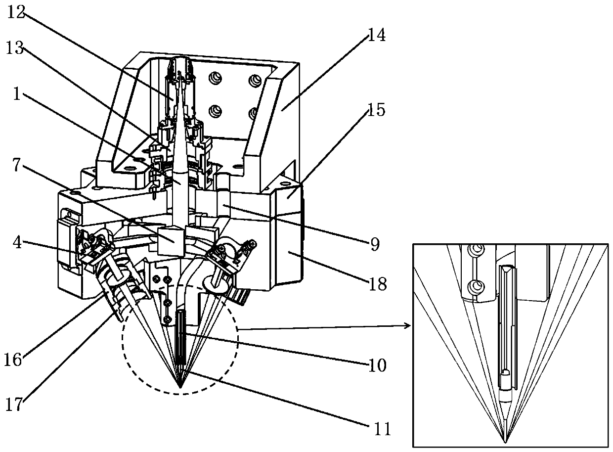
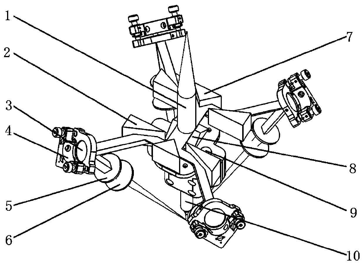
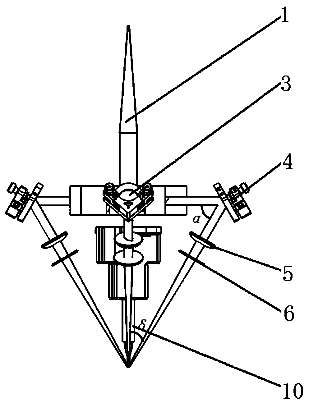
[0036] Such as figure 1 As shown, the present invention provides a coaxial wire feeding cladding head, including a connecting bracket 14, a cover 15, and a cladding head mirror cavity 18, and an optical path beam splitting unit and a wire feeding tube 10 are arranged in the cladding head mirror cavity 18, A light source collimation module 13 is arranged on the cover 15, and the wire feeding tube 10 is arranged coaxially with the collimated laser beam 1. The wire feeder 11 , the wire passes through the wire feeder 10 and the wire feeder 11 in sequence, and the adjustable mirror 3 can adjust the beam splitting to focus on the wire protruding from the wire feeder 11 .

[0037] Wherein, the collimated laser beam 1 is made of a laser as a light source, and after being collimated by the light source collimating module 13, a parallel beam is generated, and the energy distribution of the beam is uniform, and it is a flat-top distributed circular spot; the connecting bracket 14 is used...

Embodiment 2

[0050] This embodiment provides an optical path spectroscopic unit. On the basis of Embodiment 1, the spectroscopic reflector of this embodiment is a triangular pyramid, the incident laser beam is incident on the apex of the spectroscopic reflector, and the triangular pyramid can collimate the laser beam Evenly divided into three one-third light beams and the one-third light beams are located on the same plane, and the one-third light beams are irradiated to the adjustable reflector.

Embodiment 3

[0052] This embodiment provides an optical path spectroscopic unit. On the basis of Embodiment 1, the spectroscopic reflector of this embodiment is a quadrangular pyramid, and the incident laser beam is incident on the apex of the spectroscopic reflector. The quadrangular pyramid can collimate the laser beam Evenly divided into four quarter beams and the quarter beams are located on the same plane, and the quarter beams are irradiated to the adjustable reflector.


PUM


Abstract

The invention discloses a light path light split unit and a coaxial wire feed cladding head thereof. The light path light split unit comprises a plurality of adjustable reflecting mirrors and at leastone-stage light split reflecting motor, the adjustable reflecting mirrors are distributed all around the light split reflecting motors, the light split reflecting motors can divide incident light beams into a plurality of light split light beams perpendicular to the incident light beams, and each light split light beam focuses on a point through the adjustable reflecting mirrors; and the coaxialwire feed cladding head comprises a cladding head mirror cavity provided with the light path light split unit and a wire feed pipe, the wire feed pipe and collimated laser beams are coaxially arranged, the wire feed extends out of the cladding head mirror cavity, a wire sequentially passes through the wire feed pipe and a wire feed nozzle, and the adjustable reflecting mirrors can adjust the lightsplit light beams to focus on the wire. According to the light path light split unit and the coaxial wire feed cladding head thereof, light split light paths are formed through the light split unit,so that the adjustable reflecting mirrors adjust angles of the light split light beams and the wire, wire molten drops are located right above a base material molten pool in the process of coaxial wire feed, and meanwhile, it is ensured that energy of the light split light beams focusing on the top end of the wire is equally distributed.

Description

technical field [0001] The invention relates to the field of laser cladding, in particular to an optical path splitting unit and a coaxial wire feeding cladding head thereof. Background technique [0002] With the rapid development of high-power fiber lasers in the past decade, laser surface modification, such as laser surface strengthening, laser surface alloying, and laser cladding, have been widely used in the automotive and aerospace fields. Laser cladding and laser multi-layer cladding technology use laser beams to melt wire (or powder) and thin-layer substrate materials. After rapid solidification, a cladding layer with extremely low dilution and roughly the same composition as the substrate is formed. The method is called laser surface cladding. Through wire feeding (or powder feeding) cladding, the cladding layer and the base material form a metallurgical bond, thereby improving the wear resistance, corrosion resistance, heat resistance and oxidation resistance of t...

Claims


Application Information

Patent Timeline
Patent Type & Authority Applications(China)
IPC IPC(8): B23K26/20B23K26/14B23K26/046B23K26/70
CPCB23K26/20B23K26/14B23K26/046B23K26/703G02B27/143G02B27/106B23K26/34B23K26/147B23K26/0652B23K26/0643B23K26/067B23K26/0608B23K26/342G02B7/182G02B19/0019G02B19/0047G02B26/0816G02B27/149G02B27/30
Inventor 马修泉周邵巍米高阳许天宇刘庆
Owner HUAZHONG UNIV OF SCI & TECH
Why Eureka
Try Eureka