
Magneto-rheological polishing device and polishing method for dynamic magnetic field

A technology of magnetorheological polishing and dynamic magnetic field, which is applied in the direction of grinding drive device, grinding/polishing equipment, surface polishing machine tool, etc. sharpness and other problems, to achieve the effect of improving polishing efficiency, sufficient chemical reaction, and improving polishing effect

Pending Publication Date: 2020-04-28
GUANGDONG UNIV OF TECH
View PDF3 Cites 10 Cited by
  • Summary
  • Abstract
  • Description
  • Claims
  • Application Information

AI Technical Summary

Problems solved by technology

However, because the traditional magnetorheological polishing belongs to point contact polishing, it is necessary to control the polishing wheel to scan along the workpiece surface according to a certain trajectory to realize the processing of the entire surface, resulting in low polishing efficiency. Certain measures need to be taken to improve the efficiency of magnetorheological polishing
[0003] Chinese patent CN200610132495.9 proposes a grinding and polishing method based on the magnetorheological effect, but due to the magnetorheological effect of the static magnetic field, the polishing pad lacks the mechanism of self-dressing and self-sharpening of the abrasive, and the magnetorheological fluid under the action of the magnetic field The viscoelasticity makes the polishing pad formed by the static magnetic field force and distort the surface of the workpiece after processing, making it difficult to keep the performance of the processed workpiece stable; Chinese patent CN201710085353. If the damage is extremely small, it will take a long time to remove it only by the mechanical action of magnetorheological polishing; a cam-driven magnet type magnetorheological fluid dynamic pressure polishing device and polishing method proposed in Chinese patent CN201710094137.1 are due to the use of Because the magnets that generate the magnetic field are difficult to disassemble, it is difficult to clean the polishing disc, which affects the next polishing to a certain extent

Method used


Image

  • Magneto-rheological polishing device and polishing method for dynamic magnetic field
  • Magneto-rheological polishing device and polishing method for dynamic magnetic field
  • Magneto-rheological polishing device and polishing method for dynamic magnetic field

Examples


Embodiment 1

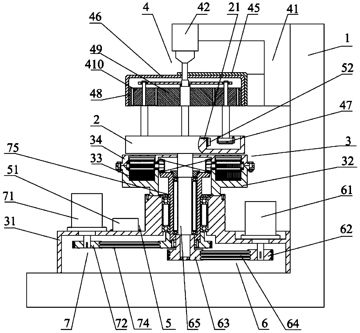
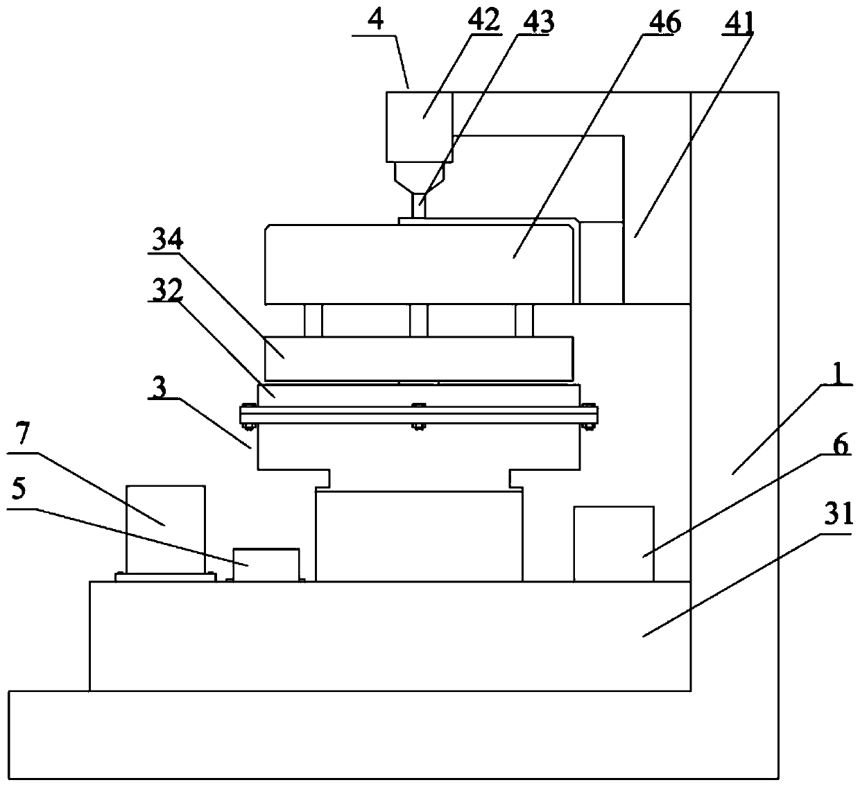
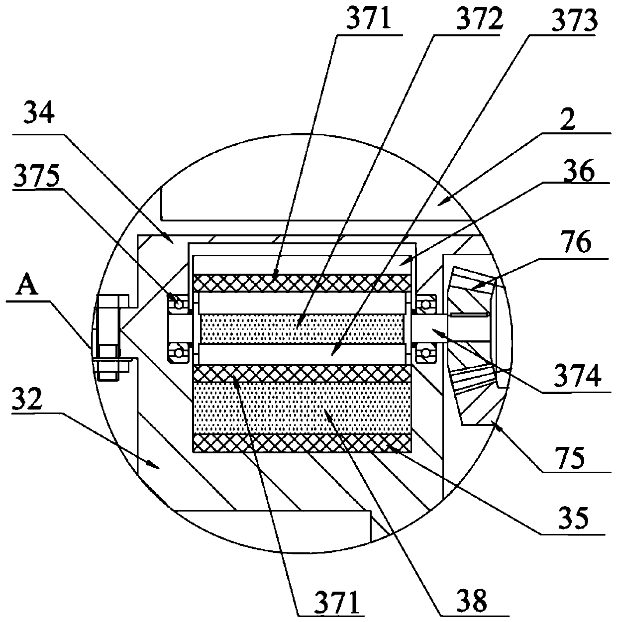
[0042] Such as Figure 1 to Figure 9 Shown is an embodiment of the dynamic magnetic field magnetorheological polishing device of the present invention, including a base 1, a polishing disc 2, a dynamic magnetic field generating assembly 3, a workpiece clamping assembly 4, an ultrasonic assembly 5, and a device for driving the polishing disc 2 to rotate. The first drive assembly 6 and the second drive assembly 7 for driving the dynamic magnetic field generating assembly 3 to rotate: the workpiece clamping assembly 4 is installed on the base 1 and the workpiece clamping assembly 4 is arranged above the polishing disc 2, the polishing disc 2 and the second A driving assembly 6 is connected, and the moving magnetic field generating assembly 3 is connected with the second driving assembly 7, and the moving magnetic field generating assembly 3 is arranged below the polishing disc 2 and forms a dynamic magnetic field in the polishing disc 2, the first driving assembly 6, the second dr...

Embodiment 2

[0051] This embodiment is an embodiment of the polishing method of the dynamic magnetic field magnetorheological polishing device of Embodiment 1, including the following steps:

[0052] S10. Install the workpiece to be processed on the chucking disc 47, and adjust the gap between the workpiece to be processed and the polishing disc 2 through the frame 41;

[0053] S20. Configure a magnetorheological polishing solution and add the magnetorheological polishing solution to the polishing disc 2, and add a catalyst to the magnetorheological polishing solution;

[0054] S30. Start the ultrasonic generator 51, adjust the ultrasonic frequency, and apply ultrasonic waves to the magnetorheological polishing liquid through the ultrasonic transducer 52 to accelerate the oxidation and corrosion of the surface of the workpiece to be processed;

[0055] S40. Start the second drive assembly 7 to drive the first magnetic source 37 to rotate to generate a dynamic magnetic field;

[0056] S50....


PUM

PropertyMeasurementUnit
Particle sizeaaaaaaaaaa

Abstract

The invention relates to the technical field of ultraprecision machining, in particular to a magneto-rheological polishing device and polishing method for a dynamic magnetic field. The magneto-rheological polishing device for the dynamic magnetic field comprises a base, a polishing disk, a dynamic magnetic field generation assembly, a workpiece clamping assembly, an ultrasonic assembly, a first driving assembly and a second driving assembly, wherein the workpiece clamping assembly is mounted on the base and is arranged above the polishing disc, the polishing disc is connected to the first driving assembly, the dynamic magnetic field generation assembly is connected to the second driving assembly and is arranged below the polishing disc, the first driving assembly and the second driving assembly are mounted on the base, the ultrasonic assembly is mounted on the lateral part of the polishing disc, and a magneto-rheological polishing solution is contained in the polishing disc. A magneticchain string is rearranged by means of the dynamic magnetic field, so that a grinding material is updated and self-sharpened. A chemical reaction is fuller by means of an ultrasonic assistant chemical reaction. As a clamping disc revolves and rotates, a workpiece is in full contact with the magneto-rheological polishing solution, so that the polishing efficiency is improved.

Description

technical field [0001] The invention relates to the technical field of ultra-precision machining, and more specifically, to a dynamic magnetic field magnetorheological polishing device and a polishing method. Background technique [0002] With the increasingly widespread application of optoelectronic and microelectronic devices, higher requirements are put forward for the quality of related components. It is necessary to maximize the processing quality in the processing process. Magnetorheological polishing technology is a new type of polishing technology based on the magnetorheological effect. The optical surface processing method, the processing process is to use the high viscosity and low fluidity "flexible polishing film" formed by the magnetorheological working fluid under the high gradient magnetic field to remove the surface material of the workpiece in a small amount, with no subsurface damage, It is suitable for curved surface processing and other advantages that tr...

Claims


Application Information

Patent Timeline
IPC IPC(8): B24B1/00B24B1/04B24B27/00B24B29/02B24B41/06B24B47/12B24B47/16B24B47/22
CPCB24B29/02B24B1/04B24B1/005B24B27/0023B24B41/061B24B47/12B24B47/16B24B47/22
Inventor 潘继生蔡志航阎秋生罗斌
Owner GUANGDONG UNIV OF TECH
Learn More