Slurry separation system

A mud separation and mud technology, applied in the direction of sludge treatment, water/sludge/sewage treatment, dehydration/drying/thickened sludge treatment, etc., can solve the problem of natural sinking, affecting the construction progress and construction site environment, mud Pond occupation of construction site and other issues

Pending Publication Date: 2020-04-28
浙江金祖环境治理设备股份有限公司
View PDF0 Cites 8 Cited by
  • Summary
  • Abstract
  • Description
  • Claims
  • Application Information

AI Technical Summary

Problems solved by technology

However, since mud is generally used to assist drilling construction in the construction process of bored piles at present, a large amount of waste mud to be processed must be produced on the site after the pile is formed.
The existing technology generally adopts the method of centralized storage and treatment of waste mud on site. Because the waste mud has a large consistency, it is difficult to sink naturally and cannot be discharged directly, resulting in a large area of ​​mud pools occupying valuable construction sites, which not only affects the construction progress and

Method used


Image

  • Slurry separation system
  • Slurry separation system
  • Slurry separation system

Examples


Embodiment Construction

[0016] The mud separation system of the present invention will be further described below in conjunction with the accompanying drawings and examples:

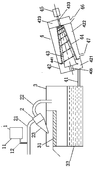
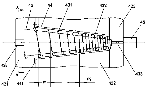
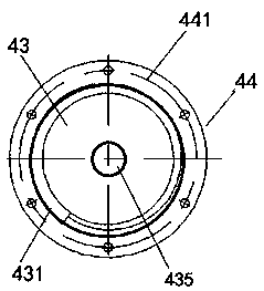
[0017] Such as Figure 1-3 As shown, a slurry separation system includes a feeding device 1 including a feeding bucket 11 and a feeding pipe 12, a cyclone desander device 2 including a slurry inlet pipe 21, a slurry outlet pipe 22 and a cyclone desander 23, including a vibration The flocculation sedimentation device 3 and the spiral separation device 4 of the screen 31, the sedimentation tank 32, and the spiral separation device 4 include the mud inlet pipe 41, the outer casing 42 containing the mud inlet 421, the middle bin 422 and the mud bin 423, and the first mud bin 423. Spiral blade 431, second spiral blade 432, input end 433 and conical screw 43 of shaft shoulder 435, filter sleeve 44, reduction motor 45, mud outlet 46 and water outlet 47; Wherein:

[0018] The feeding barrel 11 of the feeding device 1 is injected with ...


PUM


Abstract

A slurry separation system comprises a feeding device, a cyclone desanding device, a flocculation precipitation device and a spiral separation device, wherein the spiral separation device comprises aslurry inlet pipe, an outer shell, a conical screw, a filter sleeve, a gear motor, a slurry outlet and a water outlet; a feeding pipe at the bottom of the feeding barrel is connected to a slurry inletpipe, and the slurry inlet pipe is connected with a cyclone desander; the slurry outlet pipe is connected with the sedimentation tank; an inclination angle of 30-40 degrees is formed between the outer shell and the ground; the filter sleeve is fixedly arranged in the middle bin; the conical screw is arranged in the filter sleeve and penetrates out of the middle bin, and an input shaft of the conical screw is connected with the gear motor; flocculated slurry is conveyed to the slurry inlet bin through the slurry inlet pipe and extruded by the first spiral blade and the second spiral blade of the conical screw to be drained, moisture of the flocculated slurry is drained to the middle bin through the filter sleeve and then drained through the water outlet, and slurry blocks generated throughrotary extrusion are drained from the end of the conical screw, enter the slurry outlet bin and then are drained through the slurry outlet. The slurry separation efficiency is improved, the slurry water content is reduced, and the slurry treatment cost is saved.

Description

technical field [0001] The invention relates to the technical field of mud filtration treatment, in particular to a mud separation system. Background technique [0002] With the continuous enhancement of my country's economic strength, my country's infrastructure investment and real estate investment have grown rapidly. Huge investment has played a key role in the rapid development of the construction industry. Bored cast-in-situ piles are widely used in the foundation construction of a large number of deep foundations and foundation treatment. Bored cast-in-situ piles generally use mud protection technology in the construction process. The static pressure of the mud on the groove wall and the mud skin formed by the mud on the groove wall can effectively prevent the groove and hole walls from collapsing, thereby easily meeting the requirements of piling. But, generally all will use mud to assist drilling construction in the construction process of bored cast-in-situ pile a...

Claims


Application Information

Patent Timeline
IPC IPC(8): C02F11/14C02F11/121C02F11/127
CPCC02F11/121C02F11/127C02F11/14
Inventor 龚秀刚王汉宝干卫平
Owner 浙江金祖环境治理设备股份有限公司
Why Eureka
Try Eureka