Oil field two-stage dehydration system and method

A technology of oil field and dehydration equipment, which is applied in the directions of chemical dehydration/demulsification, mechanical dehydration/demulsification, dehydration/demulsification adjustment/control, etc., which can solve labor-intensive, heavy workload, machine loss, etc. problems, to achieve the effect of high degree of automation, accurate results and strong reliability

Pending Publication Date: 2020-04-28
XIAN CHANGQING TECH ENG +1
View PDF4 Cites 4 Cited by
  • Summary
  • Abstract
  • Description
  • Claims
  • Application Information

AI Technical Summary

Problems solved by technology

[0005] 1. The water-containing oil from the well site enters the ball collecting device, and the ball collecting device has no pressure display. If the pipeline is blocked, the pressure will become higher and higher, and the temperature control function, the temperature here is too high, both of which will bring production hazards;
[0006] 2. The remainder of the medicine in the dosing device at the original station needs to be manually inspected to know whether it is time to add the medicine. If the medicine is not found in time when the medicine is used up, the dosing device will keep stirring, which will easily cause machine loss, and the inspection personnel will also It takes multiple checks to grasp the exact dosing time;
[0007] 3. The heating furnaces in the original station required manual monitoring of the water level, manual ignition or shutdown at close range, and no over-temperature protection function. There were many hidden dangers, frequent inspections, and personnel safety could not be guaranteed;
[0008] 4....

Method used


Image

  • Oil field two-stage dehydration system and method

Examples


Embodiment 1

[0041]This embodiment provides a two-stage dehydration treatment system in an oil field, which includes a control cabinet and a two-stage dehydration device. The two-stage dehydration device includes a temperature sensor 20, a liquid level gauge, a pressure sensor and an electric control. The temperature sensor 20, The liquid level gauge, the pressure sensor and the electric control are all electrically connected to the control cabinet. The control cabinet includes an alarm module. Controls include motorized valves and pumps.

[0042] The present invention can improve the automation of the production process of the two-stage dehydration station through the cooperative control of each sensor and the control cabinet, realize unattended transformation, save human resources, and reduce the labor intensity of employees.

Embodiment 2

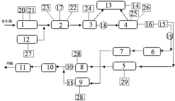
[0044] On the basis of Embodiment 1, this embodiment provides a two-stage dehydration treatment system in an oil field, the two-stage dehydration device includes a ball collecting cylinder 1, a first heating furnace 2, a buffer tank 3, and a third A phase separator 4, a tundish, an external delivery pump and a second heating furnace 10, a dosing device 12 is connected through a pipeline between the ball receiving cylinder 1 and the first heating furnace 2, and the inlet of the first heating furnace 2 A pump one 17 is arranged on the water pipeline, a pump two 18 is arranged between the buffer tank 3 and the three-phase separator 4, a pump three 19 is arranged between the three-phase separator 4 and the intermediate tank, and a pump three 19 is arranged between the three-phase separator 4 and the intermediate tank. 17. Pump two 18 and pump three 19 are electrically connected to the control cabinet.

[0045] Control the start and stop of pump one 17 through the control cabinet t...

Embodiment 3

[0047] On the basis of Embodiment 1, this embodiment provides a two-stage dehydration treatment system in an oil field, the two-stage dehydration device includes a ball collecting cylinder 1, a first heating furnace 2, a buffer tank 3, and a third A phase separator 4, a tundish, an external delivery pump and a second heating furnace 10, a dosing device 12 is connected through a pipeline between the ball receiving cylinder 1 and the first heating furnace 2, and the inlet of the first heating furnace 2 A pump one 17 is arranged on the water pipeline, a pump two 18 is arranged between the buffer tank 3 and the three-phase separator 4, a pump three 19 is arranged between the three-phase separator 4 and the intermediate tank, and a pump three 19 is arranged between the three-phase separator 4 and the intermediate tank. 17. Pump two 18 and pump three 19 are electrically connected to the control cabinet.

[0048] The ball collecting cylinder 1 is provided with a temperature sensor 20...


PUM


Abstract

The invention provides an oil field two-stage dehydration treatment system and method. The system comprises a control cabinet and a two-stage dehydration device, the two-stage dehydration device comprises a temperature sensor, a liquid level meter, a pressure sensor and an electric control part, wherein the temperature sensor, the liquid level meter, the pressure sensor and the electric control part are all electrically connected with the control cabinet, and the control cabinet is used for giving an alarm according to temperature, pressure and liquid level signals and controlling starting andstopping of the electric control part. The pressure transmitter and the temperature transmitter are arranged on the ball receiving barrel, so that the safety of a station yard and equipment are protected; a liquid level meter is added to the dosing device, and dosing time is mastered at any time; the first heating furnace is provided with a full-automatic combustor, so that remote automatic ignition and flameout protection are achieved, and the production operation safety of station personnel is improved; an associated gas outlet pressure remote transmission function is added to the buffer tank, and pressure remote transmission, over-limit alarm pump stopping, remote switching of the two pumps and emergency shutdown functions are added to the output pump, so that the number of times of on-site manual operation is reduced; meanwhile, a double-proportion drain valve is additionally arranged at the outlet of the associated gas separator to realize automatic drainage.

Description

technical field [0001] The invention belongs to the technical field of crude oil dehydration, and in particular relates to an oilfield two-stage dehydration system and method. Background technique [0002] Changqing Oilfield spans the three provinces of Shaanxi, Gansu and Ningxia. Faced with the outstanding contradiction between the rigid growth of ground facilities brought about by the continuous stable production of the oilfield and the company's labor shortage, the unattended construction has opened up a new path to alleviate the company's labor tension. It has strong reference significance for the transformation, upgrading and modernization of oilfield companies. [0003] The existing two-stage dehydration station process operation has the following problems: [0004] (1) Equipment: [0005] 1. The water-containing oil from the well site enters the ball collecting device, and the ball collecting device has no pressure display. If the pipeline is blocked, the pressure w...

Claims


Application Information

Patent Timeline
IPC IPC(8): C10G33/08C10G33/06C10G33/04
CPCC10G33/08C10G33/06C10G33/04
Inventor 池坤张平朱国承周子栋霍富永杜鑫马勇李姝仪
Owner XIAN CHANGQING TECH ENG
Why Eureka
Try Eureka