Optical fiber end face micro-cantilever sensor and preparation method thereof

A micro-cantilever beam and optical fiber end face technology, applied in the field of sensors, can solve the problems of unfavorable cantilever beam deformation, time-consuming, easy to fall off, etc., and achieve the effects of more flexible manufacturing methods, increased detection sensitivity, and flexible structural design.

Inactive Publication Date: 2020-04-28
SHENZHEN UNIV
View PDF4 Cites 6 Cited by
  • Summary
  • Abstract
  • Description
  • Claims
  • Application Information

AI Technical Summary

Problems solved by technology

For the hydrogen sensor manufactured by this method, the cantilever structure is also formed by the material of the optical fiber itself, which is relatively rigid, which is not conducive to the deformation of the cantilever beam; and the manufacturing method is time-consuming and inefficient
[0006] The silicon cantilever beam bonding method uses ultraviolet curing adhesive to directly stick commercial silicon cantilever beams on the end face of the optical fiber, or glues the silicon cantilever beam to the end face of the packaging tube, and then encapsulates the optical fiber. This adhesive production method requires high precision. The micro-manipulator is easy to fall off, the straightness of the cantilever is difficult to control, and the silicon-based material is relatively rigid, which is not conducive to the deformation of the cantilever

Method used


Image

  • Optical fiber end face micro-cantilever sensor and preparation method thereof
  • Optical fiber end face micro-cantilever sensor and preparation method thereof
  • Optical fiber end face micro-cantilever sensor and preparation method thereof

Examples


Embodiment Construction

[0040] The technical solutions of the present invention will be described in further detail below with reference to the accompanying drawings and embodiments.

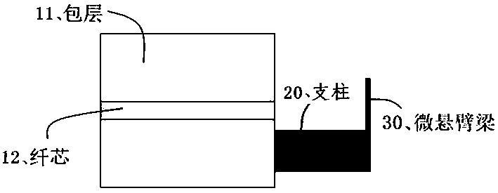
[0041] figure 1 It is a structural schematic diagram of the micro-cantilever beam sensor on the fiber end face of the embodiment of the present invention.

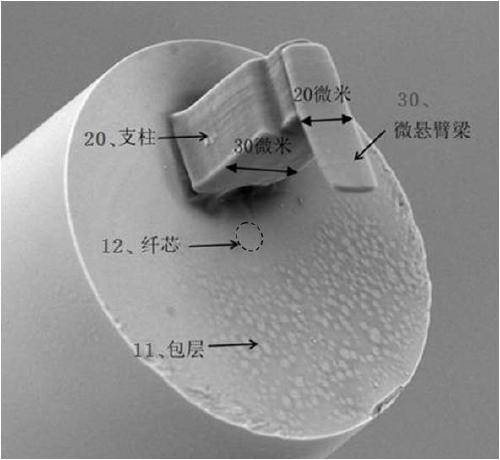
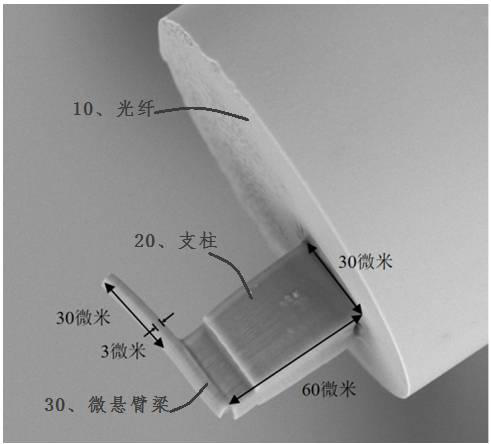
[0042] The fiber end micro-cantilever sensor includes an optical fiber 10 and a cantilever structure. Wherein, the optical fiber 10 includes an inner core 12 and a cladding 11 for covering the core 12 . The cantilever beam structure of the present application is formed on the end face of the optical fiber 10 by femtosecond laser two-photon polymerization technology.

[0043] The cantilever structure includes a strut 20 and a micro-cantilever 30 . Wherein, the first end of the pillar 20 is combined with the end face of the optical fiber 10 . One end of the micro-cantilever beam 30 is fixed to the second end of the pillar 20, and the other end of the micro-cantil...


PUM

PropertyMeasurementUnit
thicknessaaaaaaaaaa
thicknessaaaaaaaaaa
thicknessaaaaaaaaaa

Abstract

The invention discloses an optical fiber end face micro-cantilever sensor and a preparation method thereof. The optical fiber end face micro-cantilever sensor comprises an optical fiber and a cantilever beam structure. The cantilever beam structure is polymerized on one end surface of the optical fiber through a femtosecond laser two-photon polymerization technology; the cantilever beam structurehaving a polymer structure comprises a support column and a micro cantilever beam; the micro-cantilever is parallel to the end face of the optical fiber. The optical end face micro-cantilever beam prepared by a femtosecond laser two-photon polymerization technology is made of a polymer material and has elasticity higher than that of a silicon-based material, so that the detection sensitivity is greatly improved; the preparation method belongs to additive manufacturing and realizes integration of the optical fiber and the cantilever beam, and the structure is compact; no damage is caused to theoptical fiber; meanwhile, the machining time is saved, and the manufacturing mode is more flexible. The optical fiber end face micro cantilever beam cured by the femtosecond laser two-photon polymerization technology has the characteristics of small size and high elasticity, and can be applied to multiple fields.

Description

technical field [0001] The invention relates to an optical fiber end-face micro-cantilever sensor and a preparation method thereof, belonging to the technical field of sensors. Background technique [0002] Optical fiber sensors can have outstanding advantages such as high sensitivity, high precision, strong anti-interference ability, large dynamic response range, high pressure resistance, and corrosion resistance. [0003] Existing optical fiber sensors are generally made by the following methods: [0004] Femtosecond laser ablation, using femtosecond laser ultrashort pulses to directly perform subtractive manufacturing on the end face of the optical fiber. When the laser pulse is incident, the energy generated by the optical fiber material absorbing photons will quickly accumulate in the absorbing layer with a thickness of only a few nanometers. The temperature value of the electrons generated in an instant will be much higher than the melting point of the material, and t...

Claims


Application Information

Patent Timeline
Patent Type & Authority Applications(China)
IPC IPC(8): G01N21/45
CPCG01N21/45G01N2021/458
Inventor 廖常锐王义平熊聪朱梦
Owner SHENZHEN UNIV
Why Eureka
Try Eureka