Oxygen generator

An oxygen generator and oxygen technology, which is applied in the field of oxygen generators, can solve the problems of entering and affecting the long-term use of equipment, and achieve good adsorption effects, good drying and impurity removal effects, and long-lasting effects

Inactive Publication Date: 2020-05-05
HANGZHOU SHENGBO PURIFICATION EQUIP
View PDF12 Cites 3 Cited by
  • Summary
  • Abstract
  • Description
  • Claims
  • Application Information

AI Technical Summary

Problems solved by technology

Only by drying and removing impurities through a cold dryer, the treated air will still contain certain impurities and moisture, which will cause this

Method used


Image

  • Oxygen generator
  • Oxygen generator
  • Oxygen generator

Examples


Embodiment 1

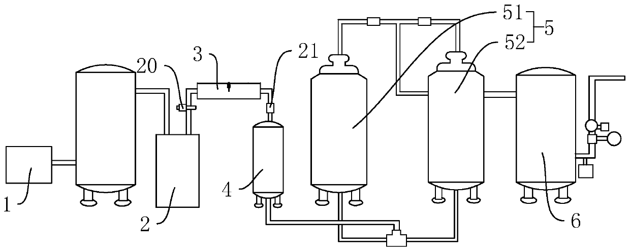
[0045] an oxygen generator such as figure 1 As shown, it includes an air compressor 1, a cold dryer 2, a filter device 3, an oil remover 4, an adsorption system 5, an oxygen buffer 6 and a controller (not shown), the air compressor 1, the cold dryer 2, The filtering device 3, degreaser 4, adsorption system 5 and oxygen buffer 6 are connected in sequence through pipelines. The adsorption system 5 includes a left adsorption tower 51 and a right adsorption tower 52. The left adsorption tower 51 and the right adsorption tower 52 are connected to the two outlets of the three-way valve through pipelines, and the inlet of the three-way solenoid valve is connected to the degreaser 4 through pipelines. export. The outlets of the left adsorption tower 51 and the right adsorption tower 52 are all connected to the oxygen buffer 6, and a check valve is connected between the left adsorption tower 51, the right adsorption tower 52 and the oxygen buffer 6, and the check valve makes the left ...

Embodiment 2

[0055] A kind of oxygen generator, the difference with embodiment one is, as Figure 6 As shown, a tank body 14 is connected between the cold dryer 2 and the filter device 3 through a conduit, the tank body 14 is set lower than the drain of the cold dryer 2, and the drain of the cold dryer 2 is connected to the The tank body 14 , the conduit connecting the tank body 14 with the filter device 3 is connected to the top of the tank body 14 .

[0056] Such as Figure 7 As shown, the bottom of the tank body 14 is communicated with a drain valve 16 . The outer wall of the tank body 14 is connected with a liquid level gauge 17 along the vertical direction. The liquid level gauge 17 is used to display the state of the water level in the tank body 14 .

[0057] Such as Figure 6 , Figure 8 As shown, the conduit connecting the tank body 14 with the cold dryer 2 is close to the bottom of the tank body 14 and penetrates into the tank body 14 to form a nozzle 18. The nozzle 18 is set ...


PUM


Abstract

The invention discloses an oxygen generator, and relates to the field of oxygen production equipment. The oxygen generator comprises an air compressor, a refrigerated air dryer, a degreaser, an adsorption system, an oxygen buffer and a controller, wherein the air compressor, the refrigerated air dryer, the degreaser, the adsorption system and the oxygen buffer are connected in sequence through pipelines; a filtering device is further connected between the refrigerated air dryer and the degreaser, the filtering device comprises a mounting box and a filtering piece, two ends of the mounting boxrespectively communicate with the refrigerated air dryer and the degreaser, the mounting box is filled with the filtering piece, and the filtering piece comprises two absorbent cotton blocks which aredistributed in the ventilation direction of the mounting box and are filled in the mounting box, and an activated carbon layer filled between the two absorbent cotton blocks. By arranging the filtering device, water and impurities in the air are further adsorbed through the water absorption cotton block and the activated carbon layer of the filtering device, so that the situation that the water and the impurities enter the degreaser or an adsorption system is reduced, the drying and impurity removing effects are better, and the overall service life is longer.

Description

technical field [0001] The invention relates to the field of oxygen generators, more specifically, it relates to an oxygen generator. Background technique [0002] Oxygen generators usually adopt the principle of pressure swing adsorption oxygen production. First, the compressed air passes through the pretreatment system to remove solid impurities such as oil and dust and most of the gaseous water, and enters the adsorption tower equipped with zeolite molecular sieve (ZMS). The nitrogen in the air , carbon dioxide, and water vapor are adsorbed by the adsorbent, and oxygen is separated through the adsorption bed. When the adsorbed impurities in the adsorption tower reach a certain level, they enter the atmosphere for desorption and desorption to regenerate the adsorbent. The adsorption separation system consisting of two towers and three towers is cyclically switched under the automatic control of PLC or DCS system to complete continuous oxygen production. [0003] For exam...

Claims


Application Information

Patent Timeline
IPC IPC(8): B01D53/26B01D53/047C01B13/02
CPCB01D53/265B01D53/263B01D53/047C01B13/0259C01B2210/0046C01B2210/0062C01B2210/0068C01B2210/0051B01D2257/80
Inventor 盛之圭盛文涛周炜
Owner HANGZHOU SHENGBO PURIFICATION EQUIP
Why Eureka
Try Eureka