
Efficient silicon removal device

A high-efficiency, coagulation technology, applied in the direction of special treatment targets, water pollutants, water/sewage treatment, etc., can solve the problem of low chemical utilization rate, affecting the system, coagulation flocculation tank and central diversion tube bottom mud accumulation and other problems, achieve the effects of obvious silicon removal effect, simple and quick maintenance, and reduce the probability of operation accidents

Inactive Publication Date: 2020-05-08
SHAANXI AEROSPACE ELECTROMECHANICAL ENVIRONMENTAL ENG DESIGNING INST CO LTD
View PDF7 Cites 0 Cited by
  • Summary
  • Abstract
  • Description
  • Claims
  • Application Information

AI Technical Summary

Problems solved by technology

[0005] The purpose of the present invention is to solve the shortcomings of the existing silicon removal device, such as the low chemical utilization rate, the serious mud accumulation at the bottom of the coagulation flocculation tank and the central diversion tube, which affects the normal operation of the system, and provides a high-efficiency silicon removal device. device

Method used


Image

  • Efficient silicon removal device
  • Efficient silicon removal device
  • Efficient silicon removal device

Examples


Embodiment Construction

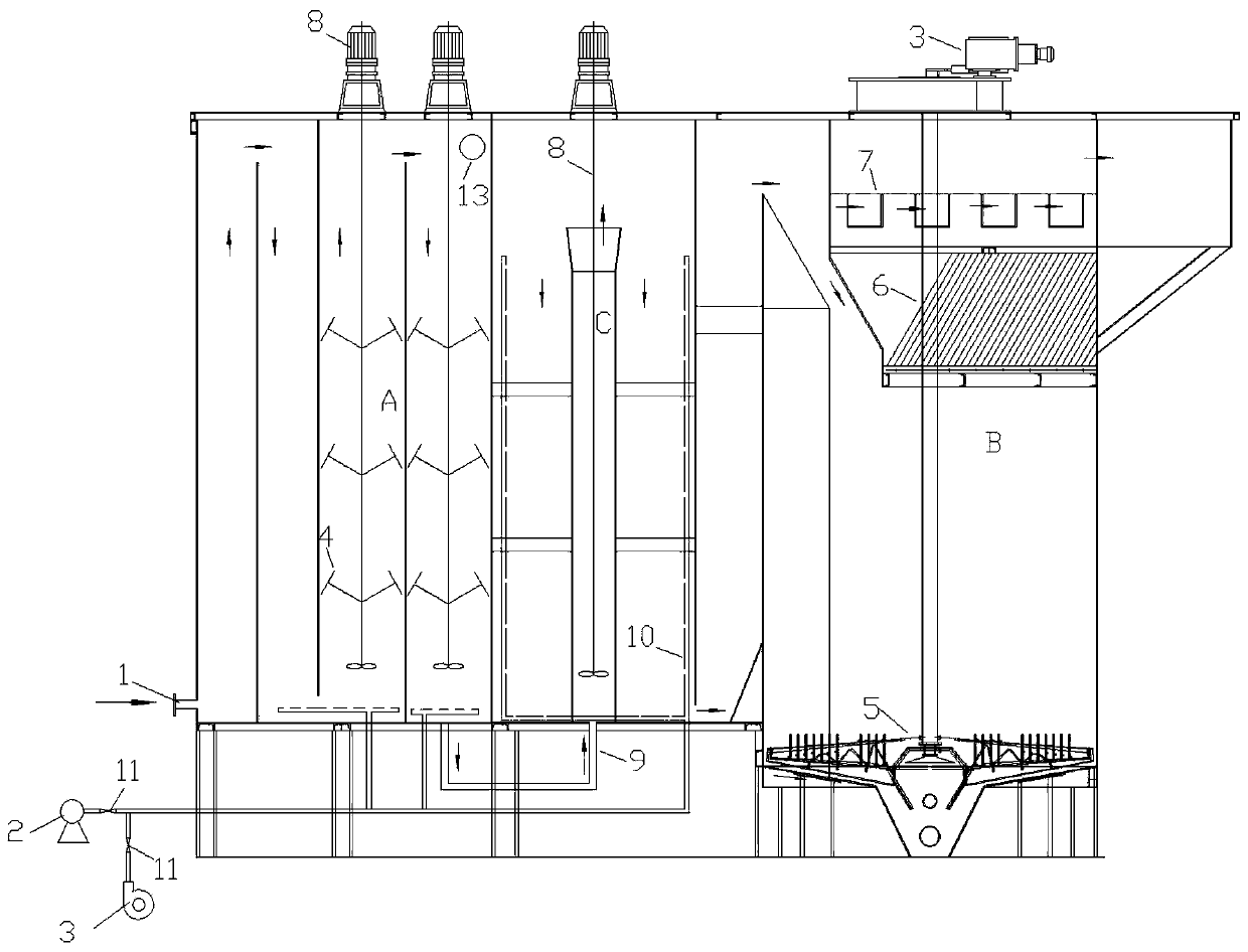
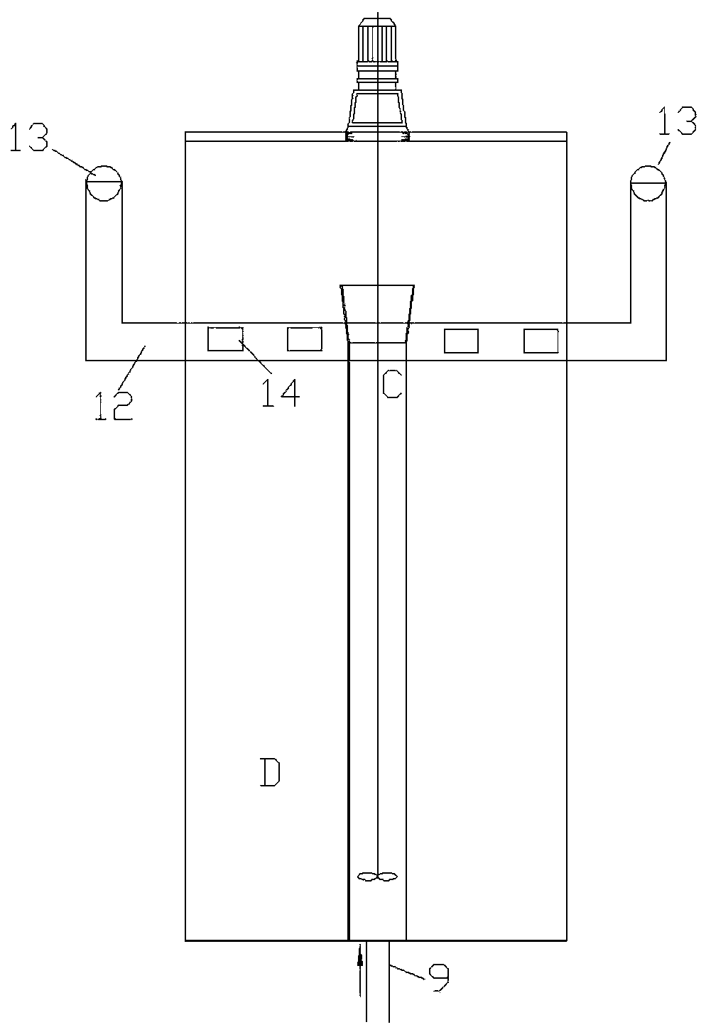
[0028] Below in conjunction with accompanying drawing and specific embodiment content of the present invention is described in further detail:

[0029] Such as Figure 1 to Figure 3 As shown, the high-efficiency silicon removal device includes a coagulation and flocculation tank A, a central guide tube C, an adjacent area D of the central guide tube, and a sedimentation tank B that are sequentially connected along the water flow direction. In addition, it also includes a T-shaped inclined plate 4, an overflow pipe 12 and a backwashing unit.

[0030] The coagulation and flocculation tank A is continuously provided with a plurality of vertical partitions, forming an "S"-shaped water flow channel in the horizontal direction, which is used to prolong the contact time between the high salt water and the chemical agent, and the area between adjacent partitions is equipped with a mixer 8 , the stirring shaft of each mixer 8 is provided with a T-shaped inclined plate 4, and the T-sha...


PUM


Abstract

The invention provides an efficient silicon removal device, and solves the problems that the chemical utilization rate of an existing device is low and sludge accumulation at the bottoms of a coagulation flocculation tank and a central guide cylinder is serious and influences the normal operation of a system. The device comprises a coagulation flocculation tank, a central guide cylinder, a centralguide cylinder adjacent region, a sedimentation tank, a T-shaped inclined plate, a backwashing unit and an overflow pipe, wherein the T-shaped inclined plate comprises a transverse plate and a connecting rod with one end connected to the middle part of the transverse plate; the other end of the connecting rod is arranged on a stirring shaft of a stirrer in the coagulation flocculation tank, and an included angle of 45-75 degrees is formed between the other end of the connecting rod and the stirring shaft; the backwashing unit comprises a water pump, a fan and a perforated aeration pipe; the perforated aeration pipe is arranged at the bottom of the coagulation flocculation tank and in the central guide cylinder adjacent region; both the water pump and the fan are connected with the perforated aeration pipe through communication pipelines, and realize water washing and wind washing of the coagulation flocculation tank and the central guide cylinder adjacent region through the perforatedaeration pipe; a first through hole is formed in the upper part of the coagulation flocculation tank; and a second through hole is formed in the side wall of the central guide cylinder adjacent region.

Description

technical field [0001] The invention relates to water treatment equipment, in particular to a high-efficiency silicon removal device for removing silicon dioxide in high-salt water. Background technique [0002] The high-density pool is an indispensable and important processing unit for the silicon removal process with high brine content. The effect of silicon removal directly affects whether the subsequent membrane system and evaporation crystallization system are blocked, and is crucial to the reliability of the entire system. The incoming water enters the coagulation and flocculation tank first, reacts by adding sodium metaaluminate, and continues to add flocculant polyaluminum (PAC) to form alum flowers, and then adds coagulant aid to the central diversion cylinder and the adjacent area of ​​the central diversion cylinder. Polyacrylamide (PAM), alum flowers further collide and grow, and the sludge and water are separated in the sedimentation tank, and the effluent flows ...

Claims


Application Information

Patent Timeline
IPC IPC(8): C02F1/52C02F101/10
CPCC02F1/5281C02F2303/14C02F2101/10
Inventor 李亮高继荣张文张建宁孙学梅李嘉刘强
Owner SHAANXI AEROSPACE ELECTROMECHANICAL ENVIRONMENTAL ENG DESIGNING INST CO LTD
Learn More