Measurement method for photon spin-orbital angular momentum joint mode and measurement system

An orbital angular momentum, joint mode technology, applied in the field of optical communication, to achieve the effect of easy integration, easy implementation, and reduced mode crosstalk

Active Publication Date: 2020-05-08
SUN YAT SEN UNIV
View PDF3 Cites 5 Cited by
  • Summary
  • Abstract
  • Description
  • Claims
  • Application Information

AI Technical Summary

Problems solved by technology

[0007] In order to solve the problem of simultaneous demultiplexing of SAM and OAM modes, the present invention provides a measurement method and measurement system of photon spin-orbital an

Method used


Image

  • Measurement method for photon spin-orbital angular momentum joint mode and measurement system
  • Measurement method for photon spin-orbital angular momentum joint mode and measurement system
  • Measurement method for photon spin-orbital angular momentum joint mode and measurement system

Examples


Embodiment 1

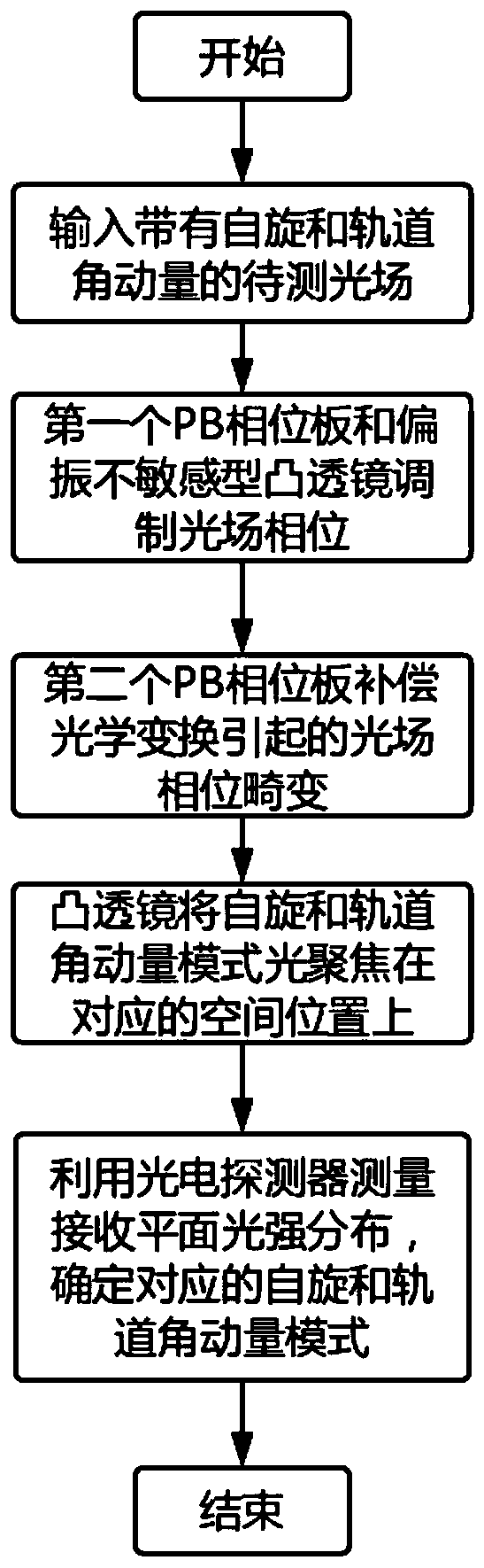
[0048] like figure 1 Shown, a kind of measurement method of photon spin-orbital angular momentum joint mode, described measurement method comprises the following steps:

[0049] S1: Input the light field with spin-orbit angular momentum to be measured vertically to the (x, y) plane, and the center of the light field is aligned with the center of the plane;

[0050] Assuming photon spin angular momentum Among them, σ=±1, which is closely related to the polarization state of the light field, σ=1 is the left-handed circular polarization state, σ=-1 is the right-handed circular polarization state; the photon orbital angular momentum Among them, l=0, ±1, ±2, ±3... are related to the helical wavefront of the light field; assuming that the wavefront phase of the input light field can be expressed as exp(ilθ); where l is the topological charge, that is, the orbit Angular momentum mode; θ is the azimuth; i is the imaginary unit.

[0051] S2: In order to make the input light intens...

Embodiment 2

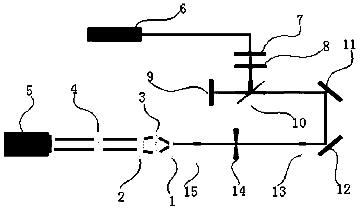
[0072] Based on the measurement method of a kind of photon spin-orbital angular momentum joint mode described in embodiment 1, such as figure 2 As shown, this embodiment also provides a photon spin-orbital angular momentum joint mode measurement system, including a PB phase modulation module, a Fourier transform module, and a light intensity detection module based on spiral coordinate transformation;

[0073] The PB phase modulation module includes a first PB phase plate 1 and a second PB phase plate 2 for modulating the light field phase;

[0074] Wherein, the first PB phase plate 1 is located on the (x, y) plane, and the first PB phase plate 1 will introduce a phase modulation Q to the left-handed circularly polarized incident light with a helical wavefront L (x,y), introduces a phase modulation Q for a right-handed circularly polarized incident light with a helical wavefront R (x,y);

[0075] The second PB phase plate 2 is located in the (u, v) plane; the second PB phase...


PUM


Abstract

The invention discloses a measurement method for a photon spin-orbital angular momentum joint mode and a measurement system. The measurement method comprises the steps of vertically inputting a to-be-measured optical field with spin-orbital angular momentum into a plane (x, y), and enabling the center of the optical field to be aligned with the center of the plane; introducing phase modulation QL(x, y) into left-handed circular polarization state incident light with a spiral wavefront, and introducing phase modulation QR(x, y) into right-handed circular polarization state incident light with aspiral wavefront; enabling light fields with different spin angular momentum to be expanded along a spiral line and be separated to different positions on a plane (u, v); introducing a compensation phase PL(x, y) into the left-handed circular polarization incident light with the spiral wavefront, introducing a compensation phase PR(x, y) into the right-handed circular polarization incident lightwith the spiral wavefront, and converging the light fields passing through the plane (u, v) at different positions of the plane (m, n); and detecting light intensity distribution of the plane (m, n) to measure a spin-orbital angular momentum joint mode input into the light field or to demodulate the spin-orbital angular momentum joint mode input into the light field.

Description

technical field [0001] The present invention relates to the technical field of optical communication, and more specifically, relates to a measurement method and measurement system of photon spin-orbit angular momentum joint mode. Background technique [0002] In recent decades, with the continuous development of information technologies such as computers, the Internet, and the Internet of Things, global data has exploded, which poses a huge challenge to data transmission capacity. Optical communication is the main way of data transmission. It is difficult to meet the demand by using traditional multiplexing technologies including time division multiplexing, wavelength division multiplexing, polarization multiplexing and high-order modulation formats to improve its transmission capacity. [0003] Therefore, space mode division multiplexing has become a hot research direction for further improving communication capacity. Spatial mode division multiplexing means that when the ...

Claims


Application Information

Patent Timeline
IPC IPC(8): H04B10/079H04B10/2581
CPCH04B10/079H04B10/2581
Inventor 陈钰杰王柏铭闻远辉余思远
Owner SUN YAT SEN UNIV
Why Eureka
Try Eureka