
Disposable electronic hysteroscope equipment

A disposable, electronic palace technology, applied in colposcopy, endoscopy, medical science, etc., can solve the problems of large space occupation, hidden dangers of patient safety, and complicated tube body, so as to improve the heat insulation effect and reduce electromagnetic interference , Improving the effect of image quality

Pending Publication Date: 2020-05-12
安徽宇度生物科技有限责任公司
View PDF0 Cites 8 Cited by
  • Summary
  • Abstract
  • Description
  • Claims
  • Application Information

AI Technical Summary

Problems solved by technology

[0003] For a disposable electronic hysteroscope, it generally includes a tube body, a head structure and a handle. The head structure is installed on the front end of the tube body, and the handle is installed on the tail end of the tube body. Most of the head structure on the front end of the pipe body is made of plastic or metal. The head structure with this structure has the following disadvantages; 1. The heat insulation effect is poor, and the image acquisition module and the light source module are in the working process It will emit some heat, which is easily absorbed by the head structure made of plastic or metal, which brings great discomfort to the patient, and may cause burns if the circumstances are serious; 2. Poor safety performance, made of metal The resulting head structure is difficult to isolate from live surgical instruments, which brings greater safety hazards to patients; 3. Electromagnetic interference is very prone to occur, and the head structure made of metal is very easy to be affected by live surgical instruments. The electromagnetic interference caused by the instrument has seriously affected the normal operation of the surgical instrument; on the other hand, the existing tube body for the disposable electronic hysteroscope is relatively complicated as a whole and occupies a large space. The disposable electronic hysteroscope with this structure When the laparoscopy is performed on the patient's uterine cavity, it is very easy to cause secondary damage to the patient, which not only brings greater discomfort to the patient, but also increases the difficulty of the uterine cavity surgery for the medical staff.
[0004] For the disposable electronic hysteroscope control system, when performing uterine examination and treatment on patients, the first choice is to insert the disposable electronic hysteroscope into the disposable electronic hysteroscope control system, and then insert the disposable electronic hysteroscope. The head of the hysteroscope is inserted into the lesion of the patient's uterine cavity, and finally the medical staff examines and treats the patient's uterine cavity through a disposable electronic hysteroscope. The control system of the prior art cannot ensure the disposable electronic hysteroscope. problem, the safety performance of the patient cannot be ensured, which brings great inconvenience to the patient's uterine cavity examination and treatment; another, in the prior art, when the patient's uterine cavity is examined and treated, most of them are carried out The fluid channel transports the uterine distension fluid to the patient's uterine cavity. After the medical staff completes the patient's uterine cavity inspection and treatment, the suction pump will then suck out the uterine distension fluid in the patient's uterine cavity through the fluid outlet channel. During the process, the cleanliness of the uterine distension fluid in the patient's uterine cavity cannot be ensured, which means that the cleanliness of the operating environment of the medical staff cannot be ensured, which brings great inconvenience to the operation of the medical staff.

Method used


Image

  • Disposable electronic hysteroscope equipment
  • Disposable electronic hysteroscope equipment
  • Disposable electronic hysteroscope equipment

Examples


Embodiment Construction

[0050] In order to make it easy to understand the technical means, creative features, objectives and effects achieved by the present invention, the present invention will be further explained below in conjunction with specific drawings.

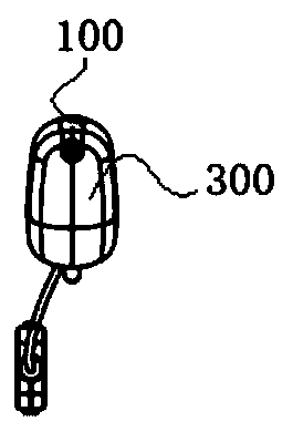
[0051] Reference Figure 1-Figure 16 As shown, the figure shows the disposable electronic hysteroscope equipment, including the hysteroscope used to insert the patient's uterine cavity to inspect and treat the patient's uterine cavity and the hysteroscope 8 to do related inspection and treatment work Control System.

[0052] The hysteroscope 8 includes a tube body 100, a head structure 200, a handle 300, and a water separator 400. The tube body 100 is made of stainless steel. The tube body 100 is provided with partitions 160 distributed along its axis. The body 100 is a stainless steel tube structure with a diameter of 5.5 mm and a wall thickness of 0.125 mm. The thickness of the partition 160 is 0.125 mm. This structure occupies a small space an...


PUM

PropertyMeasurementUnit
Diameteraaaaaaaaaa
Wall thicknessaaaaaaaaaa
Thicknessaaaaaaaaaa

Abstract

The invention discloses disposable electronic hysteroscope equipment. The disposable electronic hysteroscope equipment is characterized by comprising a hysteroscope used for being inserted into the uterine cavity of a patient to examine and treat the uterine cavity of the patient, and a control system used for controlling the hysteroscope to conduct related examination and treatment work. The hysteroscope comprises a tube body, a head structure, a handle and a water segregator, wherein the head structure comprises a head and an inserting part arranged at the tail end of the head; the front endface of the head comprises a first end face and a second end face; and an included angle between the first end face and the second end face is an obtuse angle. The control system comprises an image processing module, a display screen, a storage module, a uterine distension suction module, a disposable hysteroscope authentication module, a power supply module and a control module. The hysteroscopecan be isolated from an electrified instrument, so good safety performance is obtained; and whether the hysteroscope is used for the first time or not can be judged through the disposable hysteroscope authentication module, so repeated use of the hysteroscope is avoided, and the safety of a patient is guaranteed.

Description

Technical field [0001] The invention relates to the technical field of gynecological medical equipment, and particularly relates to disposable electronic hysteroscopy equipment. Background technique [0002] Electronic hysteroscope is a kind of instrument used for examination and treatment in the uterine cavity. When in use, the lens of the electronic hysteroscope can magnify and observe the parts in the uterine cavity. The surgical instrument can perform surgical operations on the patient's uterine cavity through an electronic hysteroscope. From an inspection point of view, electronic hysteroscopy is the first choice for gynecological bleeding diseases and intrauterine lesions. [0003] For a disposable electronic hysteroscope, it generally includes a tube body, a head structure and a handle. The head structure is installed on the front end of the tube body, and the handle is installed on the tail end of the tube body. The head structure on the front end of the tube is mostly m...

Claims


Application Information

Patent Timeline
IPC IPC(8): A61B1/00A61B1/015A61B1/018A61B1/04A61B1/303A61B17/42
CPCA61B1/00057A61B1/00064A61B1/00071A61B1/00131A61B1/015A61B1/018A61B1/04A61B1/303A61B17/42A61B2017/4216
Inventor 杨翔王臣峰郝进争
Owner 安徽宇度生物科技有限责任公司
Learn More