
Suspended filler limit denitrification method and suspended filler limit denitrification system

A technology of suspended filler and denitrification, which is applied in chemical instruments and methods, water treatment parameter control, special compound water treatment, etc. Clogging and other problems, to achieve the effect of simple composition, large processing flexibility, and improved utilization efficiency

Pending Publication Date: 2020-05-12
NORTH CHINA MUNICIPAL ENG DESIGN & RES INST
View PDF0 Cites 0 Cited by
  • Summary
  • Abstract
  • Description
  • Claims
  • Application Information

AI Technical Summary

Problems solved by technology

At present, the denitrification deep bed filter process integrating denitrification and filtration is widely used. This process is used as a technical means to ensure that the total nitrogen of sewage reaches the standard, but it has the following defects in engineering application: 1. Water quality fluctuations have a greater impact; 2. The amount of denitrification is limited, otherwise it will easily cause a large amount of biomass in the filter; The treatment effect of the system is unstable; 4. A nitrogen drive system needs to be installed to prevent air resistance; 5. The process composition is complex and the operating procedures are complex

Method used


Image

  • Suspended filler limit denitrification method and suspended filler limit denitrification system
  • Suspended filler limit denitrification method and suspended filler limit denitrification system
  • Suspended filler limit denitrification method and suspended filler limit denitrification system

Examples


Embodiment Construction

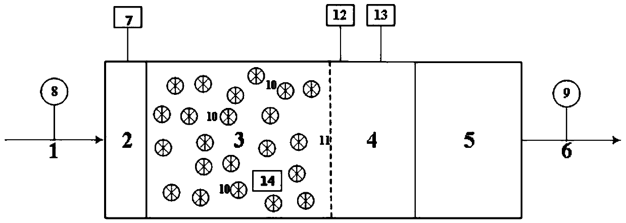
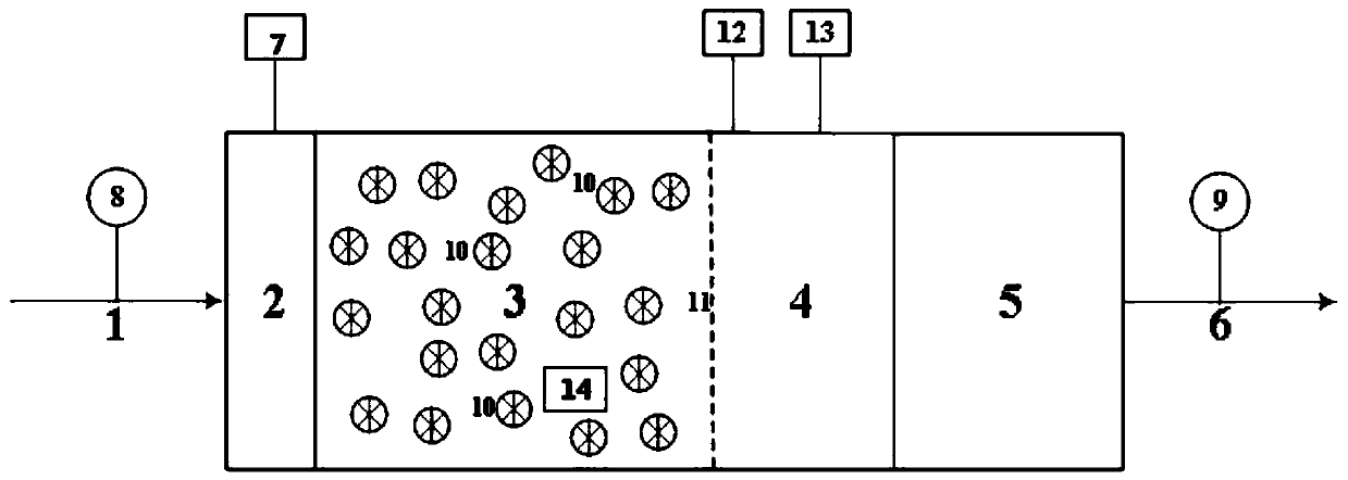
[0023] Such as figure 1 Shown: a suspended packing limit denitrification system, the system is placed behind the secondary settling tank unit and directly connected with the secondary settling tank unit. The system is composed of water inlet and distribution area 2, denitrification reaction area 3, flocculation reaction area 4 and sedimentation area 5 connected in sequence. The water inlet and distribution area is connected to the carbon source automatic control system 7 . Suspended filler 10 is added to the denitrification reaction zone, and a denitrification biofilm is attached to the surface of the suspended filler; flocculant dosing points and coagulant aid dosing points are set on the flocculation reaction zone. The system efficiently removes nitrate nitrogen in tap water under the condition of adding carbon source. According to the water quality and denitrification requirements, the proportion of suspended fillers in the denitrification reaction zone can be flexibly ad...


PUM


Abstract

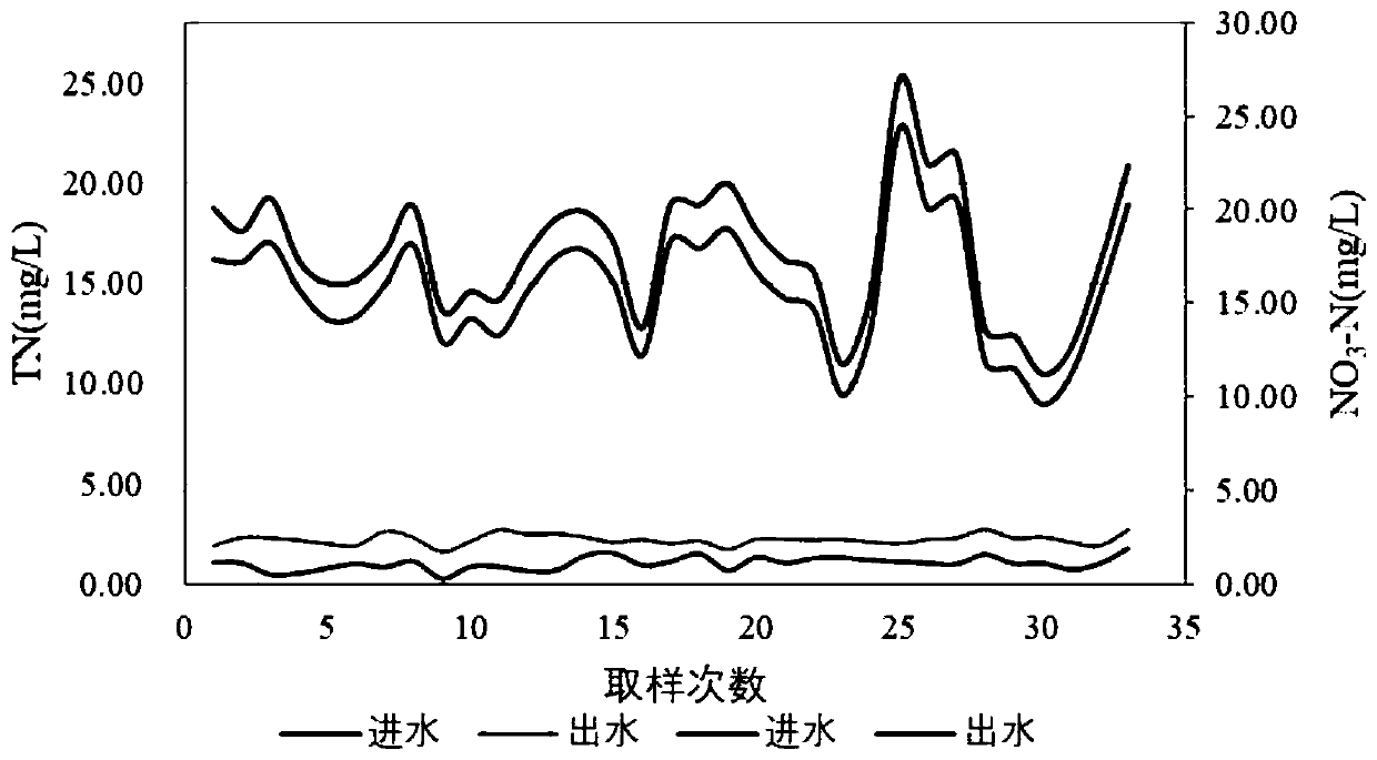
The invention discloses a suspended filler limit denitrification method. According to the method, the effluent of a secondary sedimentation tank unit enters a water inlet and distribution area, a carbon source is added, and the effluent added with the carbon source enters a suspended filler denitrification reaction area; denitrification is performed by utilizing a denitrifying biological membraneattached to the surface of a suspended filler; the effluent of the suspended filler denitrification reaction area enters a flocculation reaction area; a flocculating agent and a coagulant aid are added into the flocculation reaction area, and flocculation precipitation is performed on the suspended matters and the fallen biological membrane in the water; the effluent of the flocculation reaction area enters a precipitation area; and the finally treated effluent of the precipitation area enters a next treatment unit. The method is high in denitrification efficiency, high in denitrification loadand simple in operation, can meet the high-standard limit removal requirement of nitrogen in a sewage treatment plant, and realizes that the effluent TN is less than 3 mg / L.

Description

technical field [0001] The invention belongs to the technical field of water treatment, and relates to a method and system for extreme denitrification of suspended fillers. Background technique [0002] In the face of severe pressure to improve the water environment, in order to curb the deterioration of the local water environment, it is a development trend and an inevitable choice to improve the water environment in the future to implement higher-level discharge standards in some local water-sensitive areas or basins, especially for those that cause Nitrogen and phosphorus nutrient indicators for water body eutrophication implement high standard discharge requirements. The United States, Canada and other countries require that the standard limits of TN and TP in the effluent of sewage treatment plants in sensitive waters are less than 3mg / L and 0.1mg / L respectively. Recently, key areas and river basins such as Chaohu Lake and Kunming have promulgated and implemented strict...

Claims


Application Information

Patent Timeline
Patent Type & Authority Applications(China)
IPC IPC(8): C02F9/14
CPCC02F9/00C02F3/2853C02F1/52C02F1/001C02F2305/06C02F2209/16C02F2209/14
Inventor 申世峰郭兴芳孙永利郑兴灿熊会斌李劢吴凡松
Owner NORTH CHINA MUNICIPAL ENG DESIGN & RES INST
Learn More