Pipeline cleaning device

A technology for cleaning devices and pipes, applied in the directions of cleaning hollow objects, cleaning methods and utensils, chemical instruments and methods, etc., can solve the problems of complex driving mode, complex structure, easy damage, etc., to improve cutting efficiency and cutting effect, high efficiency Cutting and cleaning effect, the effect of reducing the complexity of the structure

Pending Publication Date: 2020-05-19
NORTHWEST INST OF ECO ENVIRONMENT & RESOURCES CAS
View PDF0 Cites 5 Cited by
  • Summary
  • Abstract
  • Description
  • Claims
  • Application Information

AI Technical Summary

Problems solved by technology

[0004] (1) The cutting effect of deposited stains is poor: Although the rotary cutter head assembly is added on the basis of high-pressure spraying, the rotary cutter head assembly specifically uses a large-leaf rubber scraper blade distributed like a windmill. On the one hand, the scraper blade is set with large leaves In the process of rotary cutting, only the end part really plays a cutting role, the structure setting is unreasonable, and the cutting efficiency is low. On the other hand, the rubber scraper blade has low rigidity and cannot effectively cut off the deposits.
[0005] (2) The structure of the driving device is complex and easy to be damaged: the driving device adopts the traditional crawler friction drive method, which has a complex structure and a complicated driving method, and the wheels and crawlers must be kept in tension and pressed against the inner wall of the pipeline at all times during work, and the parts are worn out. Severely fragile

Method used


Image

  • Pipeline cleaning device
  • Pipeline cleaning device
  • Pipeline cleaning device

Examples


Embodiment 1

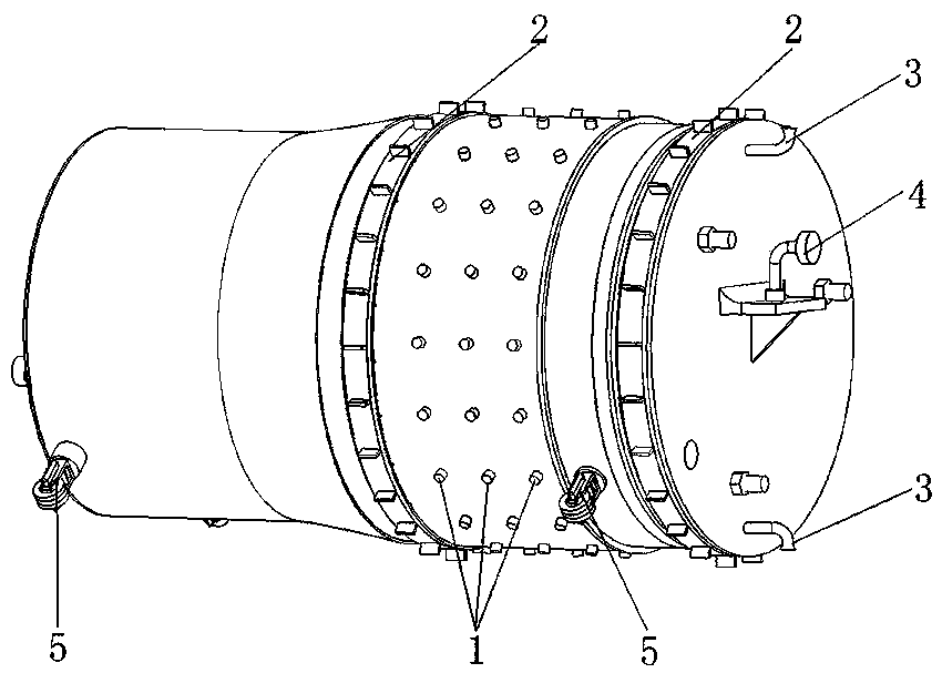
[0032] An embodiment of the present invention provides a pipe cleaning device, the overall appearance of which is nearly cylindrical, which includes the same main body frame as the traditional pipe cleaning device and the walking mechanism, rotary cutter head assembly and garbage collection device all arranged on the main frame In addition, it particularly includes a cooling device arranged on the main body frame. It can be understood that, in practical applications, these structures provided on the main body frame need to be exposed to realize corresponding functions, and the rest of the components are packaged with a protective shell.

[0033] Among them, the walking mechanism is used to drive the entire pipeline cleaning device to move axially along the pipeline; the rotary cutter head assembly is used to cut the deposited stains on the inner wall of the pipeline; the garbage recovery device is used to suck and recycle the cut garbage.

[0034] refer to figure 1 , the cool...

Embodiment 2

[0039] On the basis of the above-mentioned embodiment 1, the present invention provides a new implementation method for the rotary cutter head assembly. Compared with the prior art, the structure is reasonable, the cutting rigidity is guaranteed, and the cutting efficiency and cutting effect are greatly improved.

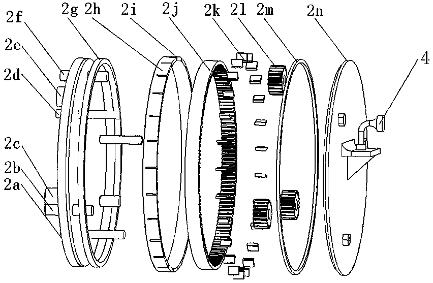
[0040] Specifically, refer to figure 1 and figure 2, the rotary cutter head assembly 2 includes an annular blade mounting frame 2h, a plurality of rigid cutting blades 2k uniformly arranged in the circumferential direction on the preset blade mounting opening 2i of the blade mounting frame 2h, and an epicyclic wheel that carries and drives the blade mounting frame 2h to rotate system structure. The main function of the rotary cutter head assembly 2 is to rigidly cut the attachments on the inner wall of the pipeline. The motor drives the fixed gear to rotate, and the fixed gear drives the epicyclic gear to move through transmission, while the epicyclic gear drives ...

Embodiment 3

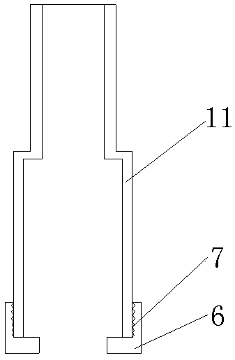
[0045] Based on the contents disclosed in the above-mentioned embodiments, the upper traveling unit of the traveling mechanism in the present invention adopts a magnetic wheel assembly. The magnetic wheel assembly mainly includes a wheel body and a rotating drive component connected to the rotation center axis of the wheel body. The wheel body has a magnet and a pipeline. (Usually iron pipes) generate magnetic attraction force, and then adsorb on the inner wall of the metal pipe to generate friction force. At the same time, due to the existence of friction force, the entire wheel body rotates under the drive of the rotating drive parts to achieve forward and backward movements. . Compared with the crawler drive mode in the prior art, the structure is simple, the drive principle is simplified, and the wear degree of related components is reduced. Considering the existence of deposits (mainly waxy layer) between the running gear and the metal pipe, the running gear should be lai...


PUM


Abstract

The invention relates to a pipeline cleaning device. The cleaning device comprises a main body frame, a traveling mechanism, a rotary cutter head assembly and a garbage recycling device, wherein the traveling mechanism, the rotary cutter head assembly and the garbage recycling device are all arranged on the main body frame; and in particular, the pipeline cleaning device also comprises a cooling device arranged on the main body frame, and cold air sprayed from the cooling device can make deposited stains cool, brittle and easy to remove, so that the cutting efficiency is obviously improved andthe cutting effect is good. When the cleaning device is applied to a permafrost region, the arrangement of the cooling device can also store cold energy for a local stratum by cooling a pipeline. Further, the rotary cutter head assembly of the cleaning device is characterized in that a plurality of rigid cutting blades are uniformly distributed in the circumferential direction and are driven to rotate by an epicyclic gear train structure, so that the structure is reasonably arranged, the cutting rigidity is guaranteed, and the cutting efficiency and the cutting effect are greatly improved; and the travelling mechanism generates friction force by virtue of magnetic force, so that the loss degree of related parts is reduced while the overall complexity is reduced, and the travelling mechanism has the barrier-crossing capability when making contact with small obstacles.

Description

technical field [0001] The invention relates to the technical field of oil and gas transmission pipeline cleaning, in particular to a pipeline cleaning device. Background technique [0002] Pipeline is one of the main ways of oil and gas transportation. After long-term operation, complex waxes, oxides, sulfides, and gravel stored in oil and natural gas adhere to the inner wall of the pipeline, which increases the friction of the inner wall of the pipeline. Resistance increases kinetic energy loss. Therefore, periodic cleaning and inspection of the pipeline is an essential work for the safe operation of the pipeline. The accumulation of waxy layers in crude oil pipelines has long been one of the problems in the industrial field. [0003] Common pipeline cleaning methods are mainly divided into chemical cleaning, mechanical cleaning, high-pressure water jet cleaning, abrasive cleaning, ultrasonic cleaning, etc. Among them, mechanical cleaning has been widely used because of ...

Claims


Application Information

Patent Timeline
Patent Type & Authority Applications(China)
IPC IPC(8): B08B9/049B08B9/051B08B13/00
CPCB08B9/049B08B9/051B08B13/00B08B9/0497B08B7/0092B08B9/035
Inventor 李国玉曹亚鹏周志伟吴晓红吴刚
Owner NORTHWEST INST OF ECO ENVIRONMENT & RESOURCES CAS
Why Eureka
Try Eureka