
KR powder spraying melt desulfurization stirring device

The technology of stirring device and melt is applied in the field of molten iron pretreatment desulfurization equipment, which can solve the problems of slow desulfurization reaction speed, low desulfurization efficiency, single stirring force direction, etc., so as to improve desulfurization efficiency, reduce sulfur weight content, and meet production needs. Effect

Inactive Publication Date: 2020-05-19
营口东邦环保科技股份有限公司
View PDF0 Cites 0 Cited by
  • Summary
  • Abstract
  • Description
  • Claims
  • Application Information

AI Technical Summary

Problems solved by technology

However, the existing KR method mechanical stirring device generally has a single direction of stirring force and insufficient stirring force, which will cause some desulfurization agents to float up into the slag without participating in desulfurization, and some desulfurization products are still in the molten iron due to insufficient floatation. To achieve the desulfurization effect, the stirring force is weak, resulting in slow desulfurization reaction speed and low desulfurization efficiency

Method used


Image

  • KR powder spraying melt desulfurization stirring device
  • KR powder spraying melt desulfurization stirring device
  • KR powder spraying melt desulfurization stirring device

Examples


Embodiment 1

[0024] The refractory protective layer of the present invention includes fused mullite, andalusite, white corundum, α-Al 2 o 3 Micropowder, 95# flake graphite, binder, steel fiber, kyanite, spinel fine powder and burnt gem; the mass ratio of the above raw materials is: 35:30:9:3:2:1:1:1 :1:1.

Embodiment 2

[0026] The refractory protective layer of the present invention includes fused mullite, andalusite, white corundum, α-Al 2 o 3 Micropowder, 95# flake graphite, binder, steel fiber, kyanite, spinel fine powder and burnt gem; the mass ratio of the above raw materials is: 41:40:12:6:3:5:3:2 :2:2.

Embodiment 3

[0028] The refractory protective layer of the present invention includes fused mullite, andalusite, white corundum, α-Al 2 o 3 Micropowder, 95# flake graphite, binder, steel fiber, kyanite, spinel fine powder and burnt gem; the mass ratio of the above raw materials is: 37:36:10:5:2.5:3:2:1.5 :1.5:1.5.

[0029] Physical and chemical performance data of the device of the present invention

[0030]

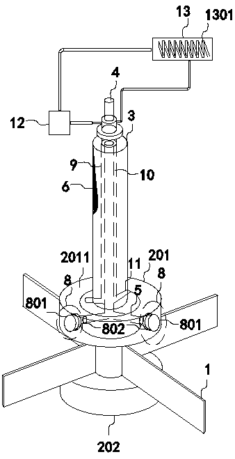
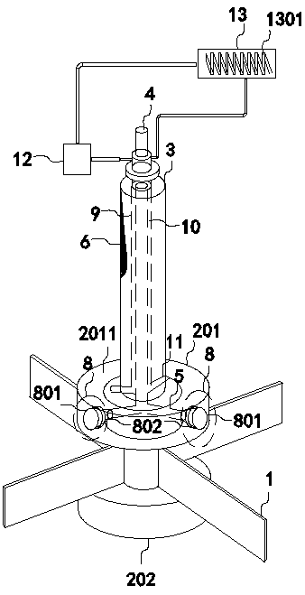
[0031] The cooling medium gas of the present invention is introduced into the annular circulation cooling cavity 2011 through the cooling gas channel 10 and the connecting pipe 11, and then passes through the turbine blade 802 on the outer wall of the first special-shaped horn-shaped tail nozzle to take away part of the heat; the heated cooling medium The gas enters the coil 1301 in the heat exchanger 13 through the communication pipe 11 and the cooling gas channel 10 for heat exchange treatment, and then is sent to the circulation pump 12 to enter the next cycle. Through the a...


PUM


Abstract

The invention belongs to the field of hot metal pretreatment desulfurization equipment, and particularly relates to a KR powder spraying melt desulfurization stirring device. A first wheel hub (201) and a second wheel hub (202) are arranged on the upper side and the lower side of a stirring blade (1); a spray pipe (4) is fixed to the middle of a stirring shaft (3) in a sleeving mode; a branch pipe(5) is fixedly arranged in the inner cavity of the first wheel hub (201); one port of the branch pipe (5) communicates with the lower port of the spray pipe (4); the other port of the branch pipe (5)communicates with a first injection mechanism (8); an annular circulating cooling cavity (2011) is formed in the first wheel hub (201); a cooling sleeve (9) sleeves the spray pipe (4) at a certain distance; a cooling gas channel (10) is formed between the inner wall of the cooling sleeve (9) and the outer wall of the spray pipe (4); and a communicating pipe (11) is arranged between the cooling gas channel (10) and the annular circulating cooling cavity (2011). The KR powder spraying melt desulfurization stirring device is simple in structure, high in stirring force and high in desulfurizationefficiency.

Description

technical field [0001] The invention belongs to the field of molten iron pretreatment desulfurization equipment, and in particular relates to a KR powder spraying melt desulfurization stirring device. Background technique [0002] With the rapid development of modern industrial production and science and technology, the requirements for steel quality are increasing day by day. For example, in order to avoid internal cracks in billets and obtain good surface quality, the sulfur content of ordinary steel is required to be less than 0.020%; in order to make structural steel have uniform mechanical properties, the sulfur content in steel is required to be less than 0.010%; in order to make oil and Natural gas pipelines, steels for petroleum refining equipment, steels for offshore oil production platforms, low-temperature steels, thick ship plate steels, and aviation steels have properties such as hydrogen-induced crack resistance, more uniform mechanical properties, and higher i...

Claims


Application Information

Patent Timeline
IPC IPC(8): C21C1/02C21C7/064C04B35/66
CPCC04B35/66C21C1/02C21C7/064
Inventor 陈学冬于林辉陈树村
Owner 营口东邦环保科技股份有限公司
Learn More