
Super-junction device and manufacturing method thereof

A technology of superjunction device and manufacturing method, which is applied in semiconductor/solid-state device manufacturing, semiconductor devices, electrical components, etc., and can solve problems such as soft breakdown and increased device leakage

Pending Publication Date: 2020-05-26
SHENZHEN SANRISE TECH CO LTD
View PDF7 Cites 0 Cited by
  • Summary
  • Abstract
  • Description
  • Claims
  • Application Information

AI Technical Summary

Problems solved by technology

[0009] The N+ cut-off region is a highly concentrated N-type region, so the P-N columns in the terminal region of the device deplete each other, and the N- epitaxial layer close to the N+ region is exhausted, and when it contacts the N+ region, an electric field will appear The peak of the intensity (increased local electric field intensity) causes the leakage of the device to increase and soft breakdown occurs
[0010] In addition, super-junction devices such as super-junction MOSFETs, due to the reduction of specific on-resistance, the chip area of ​​devices suitable for a certain current is continuously reduced. How to improve the ability of devices to withstand current shocks has always been a challenge.

Method used


Image

  • Super-junction device and manufacturing method thereof
  • Super-junction device and manufacturing method thereof
  • Super-junction device and manufacturing method thereof

Examples


Embodiment Construction

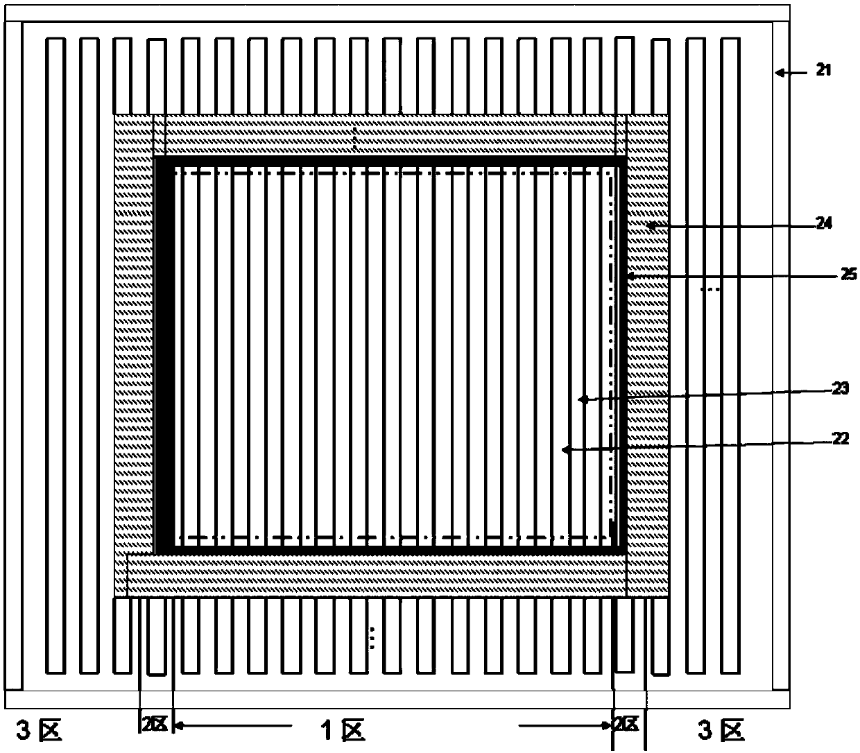
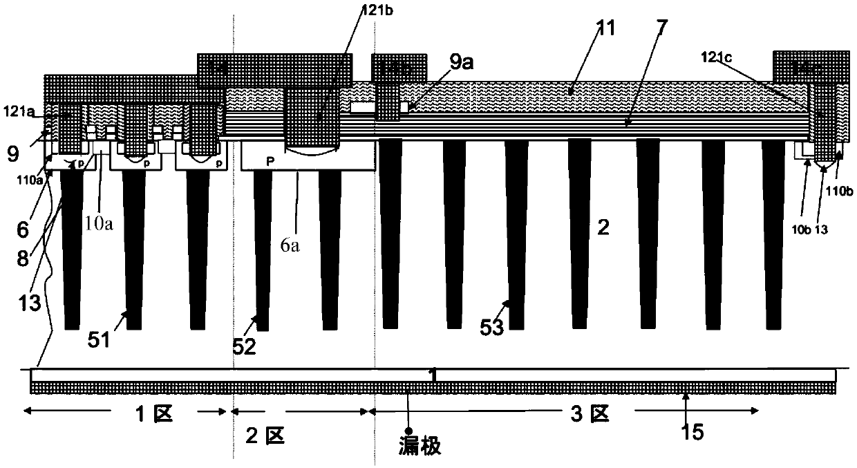
[0070] Such as figure 1 Shown is the top view of the superjunction device of the embodiment of the present invention; the general superjunction device structure includes a current flow region, a terminal region laterally subjected to a reverse bias voltage, and a transition region between the current flow region and the terminal region, a termination area surrounds the periphery of the current flow area, figure 1 Zone 1 represents the current flow region, Zone 2 represents the transition zone, and Zone 3 represents the terminal zone.

[0071] Zone 1 includes a super junction structure composed of alternately arranged P-type pillars 22 and N-type pillars 23, figure 1 Both the P-type pillars 22 and the N-type pillars 23 are strip-shaped. The N-type pillar 23 provides a conduction path when the super-junction device is turned on, and the P-type pillar 22 and the N-type pillar 23 deplete each other and bear the reverse bias together when the super-junction device is reverse-bias...


PUM


Abstract

The invention discloses a super-junction device, which is characterized in that cut-off regions of a current flowing region and a terminal region are opened by a protective epoxy film, and P-type wells are formed at the top of P-type columns of a super-junction structure of the current flowing region; JFET ion implantation is self-aligned and defined by the protective epoxy film, and a JFET regionand an electric field barrier layer surrounding the cut-off region are formed at the same time; the gate structure adopts a split-gate planar gate structure, and JFET ion implantation is carried outbefore a forming process of a gate oxide film of the split-gate planar gate, so that JFET ion implantation impurities have a structure for carrying out annealing propulsion through a thermal oxidationprocess of the gate oxide film. The invention further discloses a manufacturing method of the super-junction device. According to the invention, better diffusion of the JFET region and the electric field barrier layer can be realized, so that the on-resistance of the device can be reduced, the reliability of the device can be improved, soft breakdown at the cut-off region can be prevented, and the current impact resistance of the device can be improved. Meanwhile, the process cost cannot be increased, and the switching loss is reduced.

Description

technical field [0001] The invention relates to a method for manufacturing a semiconductor integrated circuit, in particular to a method for manufacturing a superjunction device. Background technique [0002] Existing super-junction devices include a current flow region, which is also commonly referred to as a charge flow region and a voltage-bearing terminal region, and a transition region is also included between the current flow region and the terminal region. In the current flow region, there are alternately arranged P-type columns and N-type columns, that is, P-N columns. The N-type pillars are composed of N-type epitaxial layers between the P-type pillars. Taking the striped P-N column structure as an example, there is a gate structure above each N column, and the gate structure includes a planar gate structure and a trench gate structure. For the planar gate structure, the gate structure can partially cover the surrounding P-type pillars, or not. There is a P-type w...

Claims


Application Information

Patent Timeline
IPC IPC(8): H01L29/06H01L29/40H01L29/78H01L21/336
CPCH01L29/0634H01L29/402H01L29/78H01L29/66477
Inventor 肖胜安
Owner SHENZHEN SANRISE TECH CO LTD
Learn More