High polymer material damage in-situ test device and method based on ultrasonic waves

A polymer material, in-situ testing technology, applied in the direction of material analysis, measurement device, analysis material, etc. using sonic/ultrasonic/infrasonic waves, it can solve the problem of difficulty in ensuring the accuracy of test results, increasing test difficulty and instability, The test results have a great impact on problems such as increasing the difficulty and instability of the test, improving the test efficiency, and saving the test time.

Pending Publication Date: 2020-05-29
CHINA UNIV OF PETROLEUM (EAST CHINA)
View PDF2 Cites 2 Cited by
  • Summary
  • Abstract
  • Description
  • Claims
  • Application Information

AI Technical Summary

Problems solved by technology

[0005] Ultrasonic testing is widely used in industrial non-destructive testing, but currently ultrasonic testing is mainly used for damage detection of traditional materials such as metals and rocks, and less used for polymer materials
In addition, the centering effect of the signal transmitting probe and the signal receiving probe in ultrasonic testing has a great influence on the test results. The traditi...

Method used


Image

  • High polymer material damage in-situ test device and method based on ultrasonic waves
  • High polymer material damage in-situ test device and method based on ultrasonic waves
  • High polymer material damage in-situ test device and method based on ultrasonic waves

Examples


Embodiment 1

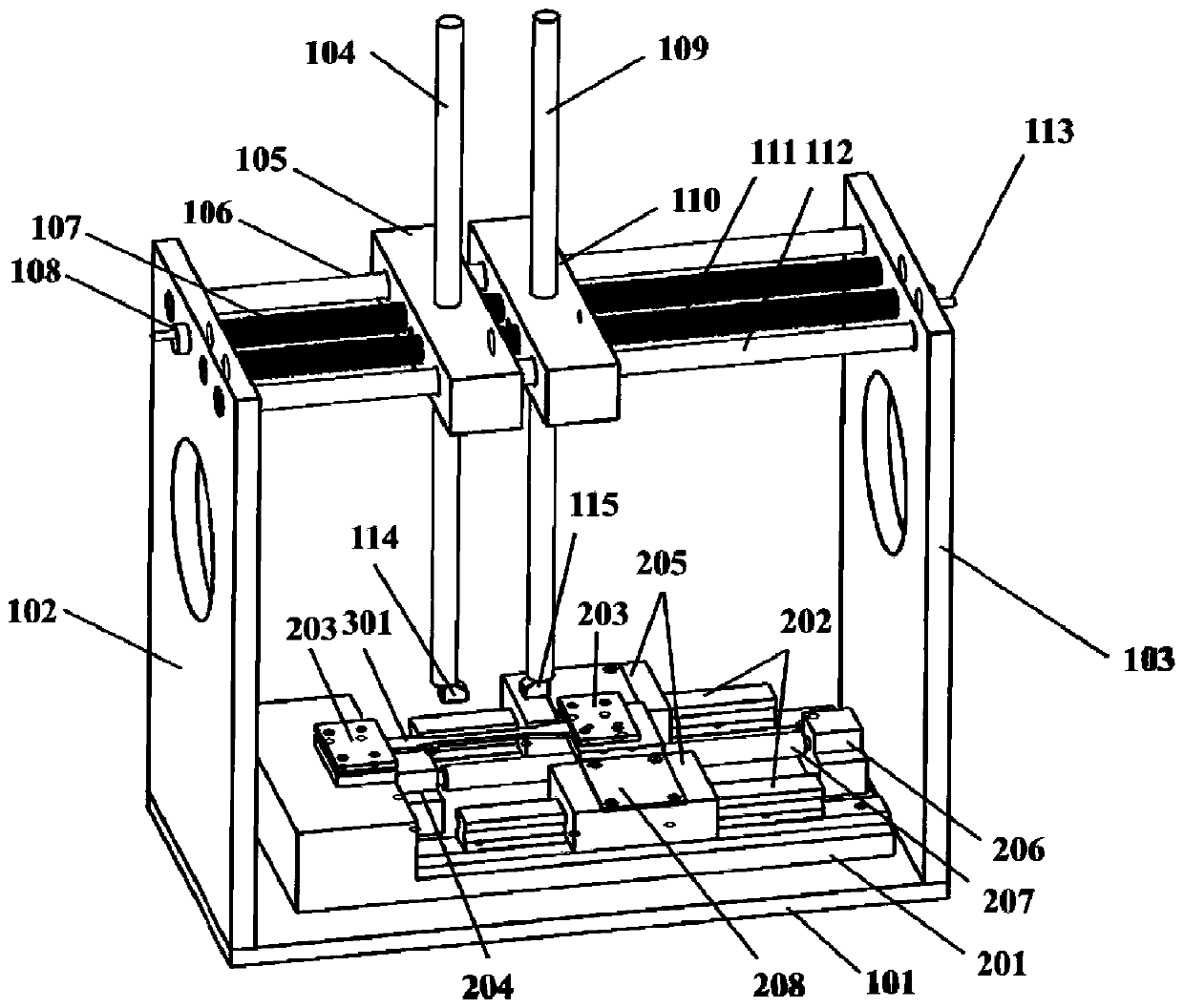
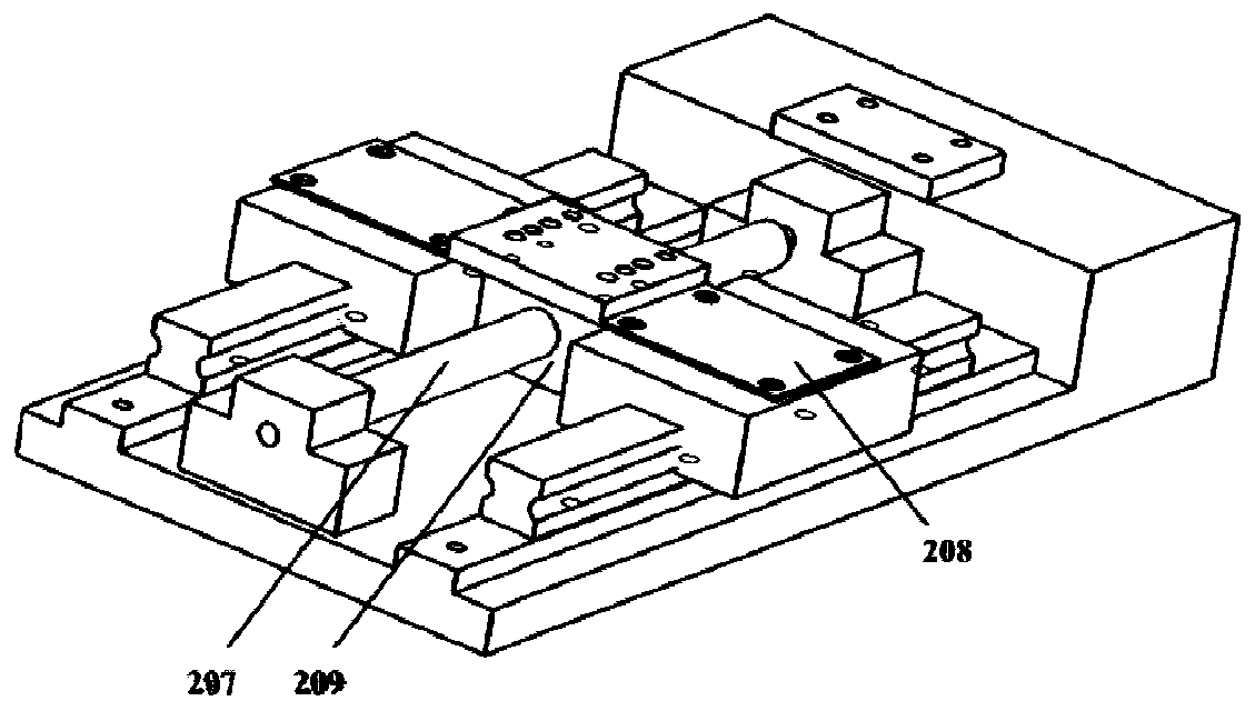
[0045] The testing device comprises an aluminum alloy bottom plate 101, a left side plate 102 and a right side plate 103, a first vertical bar 104, a first slider 105, a first cross bar 106, a first lead screw 107, and a first shaking wheel 108 to form a support. , the second vertical bar 109, the second slider 110, the second lead screw 111, the second cross bar 112, the second rocking wheel 113, the ultrasonic transmitting probe 114, the ultrasonic receiving probe 115, the in-situ stretching base 201, the slide rail 202, clamping plate 203, fixed support 204, slide rail slider 205, movable support 206, ball screw 207, slider connecting piece 208, lead screw nut seat 209 and measured polymer sample 301. In this example, taking the common polymer material-polyethylene as an example, ultrasonic waves are used to quantitatively test the damage variables of polyethylene samples.

[0046] Both sides of the top of the lead screw nut seat 209 are connected with the slide rail slider...

Embodiment 2

[0051] Embodiment 2 test process

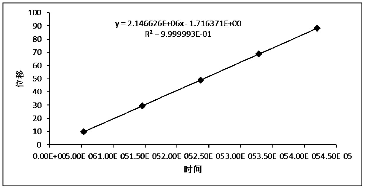
[0052] First, the polyethylene sample 301 is fixed by the sample clamping plate 203, and the ultrasonic transmitting probe 114 is fixed on the sample 301 by moving the first vertical bar 104 downward, and an appropriate amount of coupling agent is applied between the transmitting probe and the sample 301 to Improve sound wave transmission efficiency. Adjust the second rocking wheel 113 so that the second slide block 110 moves to the left to be close to the first slide block 105, and the ultrasonic receiving probe 115 is fixed on the sample 301 by moving the second vertical bar 109 downward, and the receiving probe and the test sample Apply an appropriate amount of couplant between samples 301. The ball screw 207 is controlled by the servo motor to stretch the sample 301 at a constant speed of 1 mm / min until the displacement reaches 1 mm and stops, and the ultrasonic signal is recorded. At this time, the second slider 110 is close to the fir...


PUM


Abstract

The invention relates to a high polymer material damage in-situ test device and method based on ultrasonic waves. The device comprises a mobile adjusting device, an ultrasonic transmitting probe and an ultrasonic receiving probe, wherein the moving adjusting device comprises an in-situ stretching base, a sliding rail sliding block and a sliding device, the sliding rail sliding block slides relative to the in-situ stretching base through the sliding device, the top of the in-situ stretching base and the top of the sliding rail sliding block are each provided with a clamp, the ultrasonic transmitting probe and the ultrasonic receiving probe are located above the moving adjusting device and located at the bottom of a first vertical rod and the bottom of a second vertical rod respectively, anda distance between two vertical rods is adjustable. The device is advantaged in that a damage value is calculated through the wave velocity of the ultrasonic waves, the defect that a traditional damage testing method can only measure damage variables after material deformation is overcome, and the internal damage condition of the material can be reflected more truly.

Description

technical field [0001] The invention belongs to the technical fields of polymer testing, experimental mechanics and ultrasonic non-destructive testing, and in particular relates to an in-situ testing device and method for polymer material damage based on ultrasonic waves. Background technique [0002] The information disclosed in this background section is only intended to increase the understanding of the general background of the present invention, and is not necessarily taken as an acknowledgment or any form of suggestion that the information constitutes the prior art already known to those skilled in the art. [0003] Damage mechanics characterizes damage through damage variables, and describes the damage evolution process of materials with damage evolution equations. Although damage mechanics has been developed for more than half a century, it is still in the stage of development and perfection. The understanding of the damage mechanism is still relatively insufficient,...

Claims


Application Information

Patent Timeline
IPC IPC(8): G01N3/16G01N3/02G01N3/06
CPCG01N3/16G01N3/06G01N3/02G01N2203/0003G01N2203/0017G01N2203/0037G01N2203/0244G01N2203/0658G01N2203/0682G01N29/225G01N29/265G01N29/07G01N29/4472G01N29/4445
Inventor 张毅薛世峰贾朋朱秀星叶贵根
Owner CHINA UNIV OF PETROLEUM (EAST CHINA)
Why Eureka
Try Eureka