Laser radar detection system and method with ozone absorption self-correcting function

A laser radar and ozone absorption technology, applied in the field of radar detection, can solve the problems of measurement error, limit the application of solar-blind Raman laser radar, increase the measurement cost, etc., to improve the signal-to-noise ratio, reduce the influence of background light, increase the The effect of measuring costs

Active Publication Date: 2020-05-29
HEFEI INSTITUTES OF PHYSICAL SCIENCE - CHINESE ACAD OF SCI
View PDF4 Cites 1 Cited by
  • Summary
  • Abstract
  • Description
  • Claims
  • Application Information

AI Technical Summary

Problems solved by technology

At present, the measurement data of solar-blind Raman lidar is usually corrected by using the ozone distribution data measured by another ozone lidar or model out

Method used


Image

  • Laser radar detection system and method with ozone absorption self-correcting function
  • Laser radar detection system and method with ozone absorption self-correcting function
  • Laser radar detection system and method with ozone absorption self-correcting function

Examples


Embodiment 1

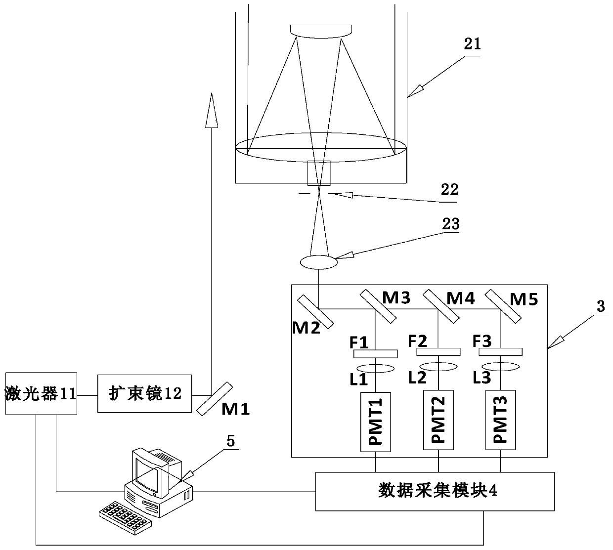
[0043] Such as figure 1 As shown, a laser radar detection system with an ozone absorption self-correction function includes a transmitting module, a receiving module, a detector module 3, a data acquisition module 4, and a host computer 5 arranged in sequence.

[0044] The emitting module is used to emit laser with a set wavelength into the atmosphere; the laser 11 includes a YAG laser machine as a laser light source, and the output of the base frequency laser is doubled and quadrupled to obtain a laser output of 266nm. The transmitting module also includes a beam expander 12 for reducing the divergence angle of the laser beam output by the laser 11, and a reflector M1 for reflecting the expanded laser into the atmosphere.

[0045] The receiving module is used to receive scattered echo signals with atmospheric information; the receiving module includes a receiving telescope 21, an aperture 22, and a collimating eyepiece 23 arranged in sequence, and the receiving telescope 21 i...

Embodiment 2

[0052] The method of using a kind of laser radar detection system with ozone absorption self-correction function described in embodiment 1 may further comprise the steps:

[0053] S1. The upper computer 5 obtains the vibration-rotation Raman scattering echo signal intensity function of water vapor molecules, nitrogen molecules and oxygen molecules;

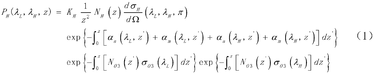
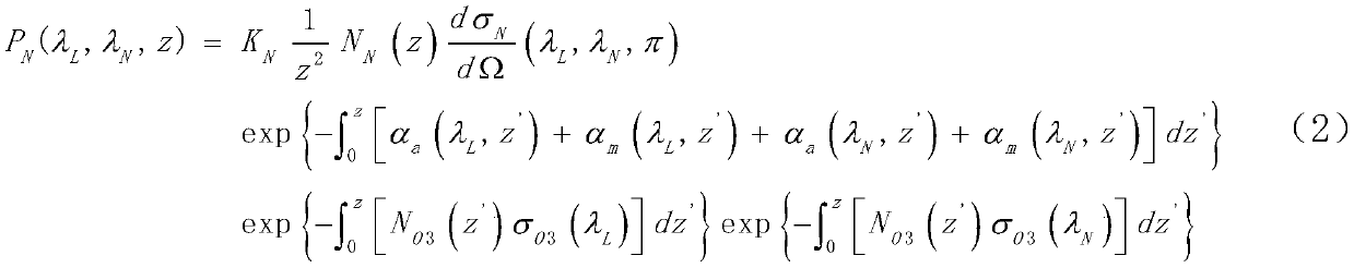
[0054] Specifically, the vibration-rotational Raman scattering echo signal intensity functions of water vapor molecules, nitrogen molecules and oxygen molecules are expressed as:

[0055]

[0056]

[0057]

[0058] Among them, P H (λ L ,λ H ,z), P N (λ L ,λ N , z) and P O (λ L ,λ O , z) are the vibration-rotational Raman scattering echo signal strengths of water vapor molecules, nitrogen molecules and oxygen molecules received by the lidar; K H 、K N and K O are the system constants of the vibration-rotational Raman scattering echo signal receiving channels of water vapor molecules, nitrogen molecules and oxygen...


PUM


Abstract

The invention discloses a laser radar detection system and method with an ozone absorption self-correcting function. The system includes a detector module, wherein the detector module comprises threedichroic mirrors and three detector units, each dichroic mirror divides a light beam into two paths, one path is reflected to the corresponding detector unit, the other path is reflected to the next dichroic mirror for beam splitting, and the three detector units correspondingly comprise vibration-rotation Raman scattering echo signals for receiving water vapor molecules, nitrogen molecules and oxygen molecules. A channel for receiving an oxygen molecular vibration-to-Raman scattering echo signal is added in the solar blind water vapor Raman laser radar, the laser radar directly measures Ramanscattering echo signals of water vapor molecules, nitrogen molecules and oxygen molecules, a hardware basis is provided for obtaining the vertical distribution of the water-vapor mixing ratio withoutthe measurement of other equipment or the inversion of the ozone concentration distribution from the measurement signal of the solar blind laser radar so that the measurement cost is reduced, and themeasurement precision is improved.

Description

technical field [0001] The invention relates to the technical field of radar detection, in particular to a laser radar detection system and method with an ozone absorption self-correction function. Background technique [0002] Raman lidar is an effective tool for measuring the high-resolution spatio-temporal distribution of water vapor in the boundary layer, and has important application value for studying various physical processes in the boundary layer. However, due to the very weak Raman scattering echo signal of water vapor, its detection ability is greatly limited due to the interference of background light during the day. In order to improve the detection ability of Raman lidar in the daytime, laser emitting devices with large pulse energy, receiving telescopes with large aperture and small field of view, and narrow-band interference filter F are generally used, so the volume and weight of Raman lidar are relatively large. , the cost is relatively high, subject to ce...

Claims


Application Information

Patent Timeline
IPC IPC(8): G01S7/497G01S17/95G01S7/48G01N21/65
CPCG01S7/497G01S17/95G01S7/4802G01N21/65Y02A90/10
Inventor 吴德成刘东王邦新钟志庆邢昆明谢晨波王珍珠王英俭
Owner HEFEI INSTITUTES OF PHYSICAL SCIENCE - CHINESE ACAD OF SCI
Why Eureka
Try Eureka