Linearized optical signal transmission system of electronic transformer

An electronic transformer and transmission system technology, applied in electromagnetic wave transmission system, transmission system, optical fiber transmission, etc., can solve the problems of increasing DC reference signal compensation amount, heavy workload, and high difficulty in implementation, and achieve the goal of offsetting LED luminous characteristics Change, strong engineering practicability, simple circuit to achieve the effect

Active Publication Date: 2020-05-29
SHANDONG UNIV OF TECH
View PDF8 Cites 2 Cited by
  • Summary
  • Abstract
  • Description
  • Claims
  • Application Information

AI Technical Summary

Problems solved by technology

and further by Image 6 It can be seen that the method directly drives the light-emitting diode, which is limited by the light-emitting mechanism of the light-emitting diode, and there is a light-emitting dead zone, so the input current of the light-emitting diode has a nonlinear relationship with the output optical power, so this scheme has not been realized. Linear Transmission of Signals
[0004] (2) The technical solution disclosed in the Chinese patent with the application number 201410379248.3 and the patent name "Analog Electrical Signal Transmission Method Applied to Current Transformers" also adopts the design of directly driving light-emitting diodes to emit light, and discloses that a DC reference The signal processing method that the signal is transmitted together with the signal to be measured is used to correct the influence of attenuation and external factors on the analog optical signal to improve the measurement accuracy, but these methods do not consider solving the nonlinear problem of light emitting diodes, so it is difficult to achieve high precision
[0005] (3) The application number is 201410379248.3, the patent name is "analog electrical signal transmission method applied to current transformer", the application number is 201510102017.2 and the patent name is "a signal transmission method for current transformer" Chinese patent document In the disclosed technical method, the design scheme of directly driving the light-emitting diode to emit light is also adopted. In addition to not realizing the linear transmission of the signal, the technical scheme also needs to measure and calibrate each set of devices in advance, and the workload is relatively large. Therefore, its application It is difficult to achieve high measurement accuracy when
The common disadvantage is that it is necessary to design a light-emitting diode device with monitoring function, which leads to high system cost, and t

Method used


Image

  • Linearized optical signal transmission system of electronic transformer
  • Linearized optical signal transmission system of electronic transformer
  • Linearized optical signal transmission system of electronic transformer

Examples


Embodiment 1

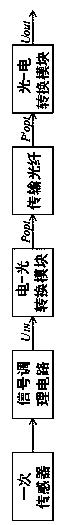
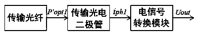
[0032] Such as figure 1 As shown, a linearized optical signal transmission system of an electronic transformer includes a primary sensor, a signal conditioning circuit, an electro-optical conversion module, a transmission optical fiber and a photoelectric conversion module. The primary sensor is connected to the input end of the signal conditioning circuit, the output end of the signal conditioning circuit is connected to the input end of the electro-optic conversion module, the output end of the electro-optical conversion module is connected to the input end of the transmission fiber (the transmission fiber is located at the connection end of the high-voltage side), the transmission fiber The output end (the connection end of the transmission fiber at the low-voltage side) is connected to the input end of the photoelectric conversion module, and the output end of the photoelectric conversion module outputs the signal.

[0033] After the primary sensor collects the electrical...

Embodiment 2

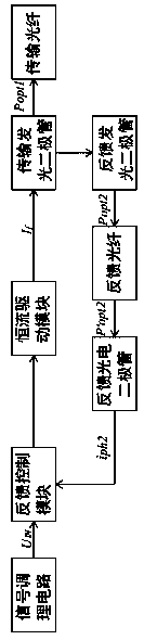
[0049] The difference between this embodiment and Embodiment 1 is that in this embodiment, the difference between the voltage signals at both ends of the input feedback control module is used to realize the voltage signal U IN and transmit the luminous power of the LED P opt1 There is a linear relationship between the two.

[0050] Such as Figure 5 As shown, an electrical signal conversion module is set in the feedback loop, and the electrical signal conversion module is located between the feedback photodiode and the feedback control module. The feedback photodiode generates a current signal after being excited by the light signal, and the current signal passes through the electrical signal on the high voltage side. The conversion module converts the feedback voltage into the other input terminal of the feedback control module.

[0051] The specific working process and working principle are as follows:

[0052] It can be seen from the description of the embodiment that ...


PUM


Abstract

The invention discloses a linearized optical signal transmission system of an electronic transformer, and belongs to the technical field of electrical engineering measurement. The high-voltage side and the low-voltage side are connected through a transmission optical fiber, and the system is characterized in that an electro-optical conversion module comprises a feedback control module; the feedback control module controls a transmission light-emitting diode and a feedback light-emitting diode to flow through driving currents with the same magnitude, and an optical signal emitted by the transmission light-emitting diode is connected with an interface, located on the high-voltage side, of the transmission optical fiber; a feedback loop is further arranged on the high-voltage side, optical signals emitted by the feedback light-emitting diode are converted into feedback voltage through the feedback loop, and the feedback voltage is connected with the other input end of the feedback controlmodule. According to the linearized optical signal transmission system of the electronic transformer, the feedback control module and the feedback loop connected with the feedback control module arearranged, so the size to be measured on the high-voltage side is linearly expressed through the luminous intensity of the light emitting diode, the complexity of the system is reduced, and the reliability is higher.

Description

technical field [0001] The invention relates to a linearized optical signal transmission system of an electronic transformer, which belongs to the technical field of electrical engineering measurement. Background technique [0002] In the field of electrical measurement, due to the advantages of optical fiber with good insulation performance, wide frequency band, and anti-interference, the electrical information (such as voltage and current) collected on the high-voltage side is converted into optical signals and transmitted to the low-voltage side by optical fiber. In the current technical application, there are mainly two ways to transmit optical signals through optical fibers: digital optical signal mode and analog optical signal mode. The analog optical signal method has the following advantages over the digital optical signal: First, since there is no need for A / D sampling on the high voltage side, it can completely retain the waveform information of the high voltage to...

Claims


Application Information

Patent Timeline
IPC IPC(8): H04B10/25H04B10/079
CPCH04B10/07955Y04S40/124
Inventor 王玮张圣鹏孙中玉
Owner SHANDONG UNIV OF TECH
Why Eureka
Try Eureka