Connecting structure, connecting method and application of quartz tuning fork and base

A technology of quartz tuning fork and connection structure, which is applied in the direction of speed measurement by gyro effect, gyroscope/steering sensing equipment, measuring device, etc., which can solve the problems of thermal expansion coefficient mismatch, thermal stress, and gas release, etc., to ensure acceptable , reduce stress, reduce the effect of displacement

Active Publication Date: 2020-06-09
BEIJING CHENJING ELECTRONICS
View PDF14 Cites 4 Cited by
  • Summary
  • Abstract
  • Description
  • Claims
  • Application Information

AI Technical Summary

Problems solved by technology

[0004] Therefore, the technical problem to be solved by the present invention is to overcome the problem that the quartz and the base material in the prior art are connected by epoxy resin insulating adhesive glue, and the heat generated due to the mismatch between the thermal expansion coefficient of the epoxy resin and the quartz and the base material Stress, at the same time will release the defect of gas over time, so as to provide a connection structure and connection method of the quartz tuning fork and the base

Method used


Image

  • Connecting structure, connecting method and application of quartz tuning fork and base
  • Connecting structure, connecting method and application of quartz tuning fork and base
  • Connecting structure, connecting method and application of quartz tuning fork and base

Examples


Embodiment 1

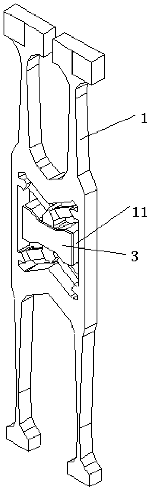
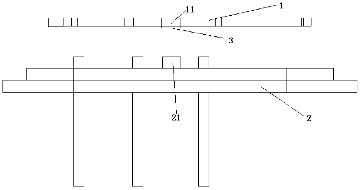
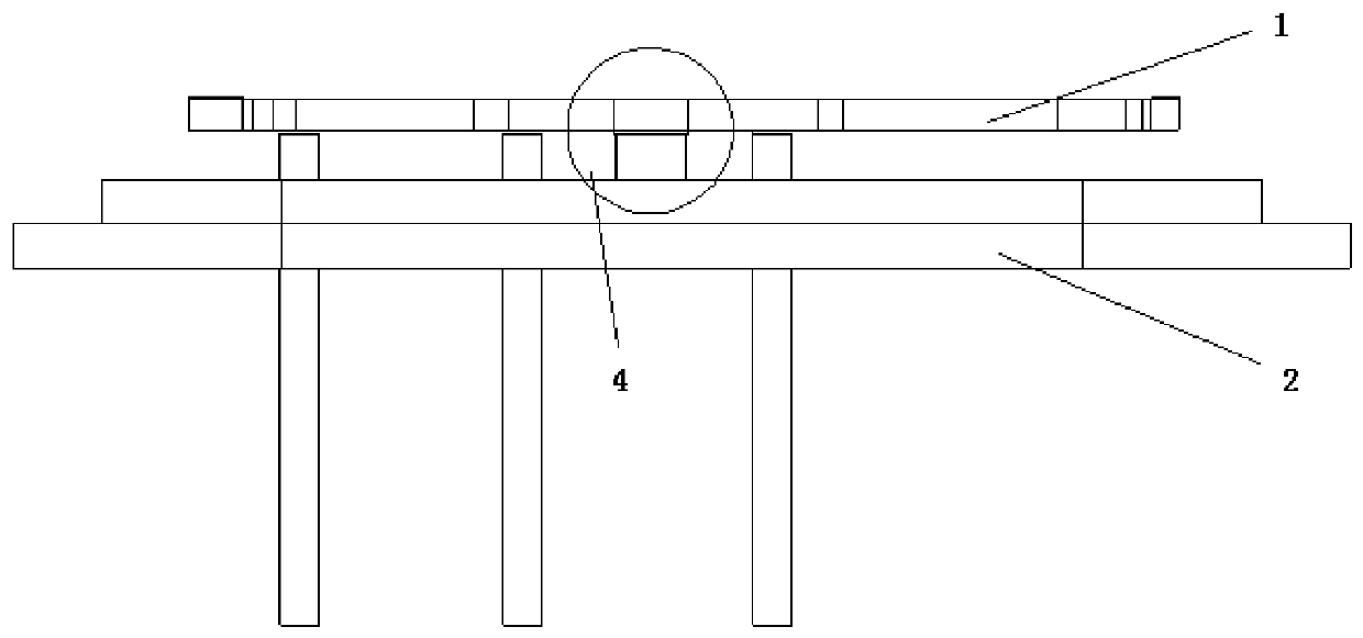
[0056] This embodiment provides a method for connecting a quartz tuning fork to a base, such as Figure 1-Figure 6 As shown, it specifically includes the following steps:

[0057] (1) On the central island 11 of the quartz tuning fork 1, magnetron sputtering is used to sequentially deposit a 20nm Cr layer 31 and a 6000nm first Au layer 32;

[0058] (2) The structure obtained in step (1) is precisely defined by using a photolithography process, so that the area corresponding to the target structure is covered by photoresist;

[0059] (3) A wet etching process is adopted for the Cr layer 31 and the first Au layer 32, and after the etching is completed, the photoresist is removed to form a target pattern;

[0060] (4) Precisely define the structure obtained in step (3) by photolithography, so that the region corresponding to the target structure is not covered by photoresist;

[0061] (5) adopt thermal evaporation to deposit the second Au layer 34 of the Sn layer 33 of 4000nm a...

Embodiment 2

[0073] This embodiment provides a method for connecting a quartz tuning fork to a base, such as Figure 1-Figure 6 As shown, it specifically includes the following steps:

[0074] (1) On the central island 11 of the quartz tuning fork 1, magnetron sputtering is used to sequentially deposit a 19nm Cr layer 31 and a 6300nm first Au layer 32;

[0075] (2) The structure obtained in step (1) is precisely defined by using a photolithography process, so that the area corresponding to the target structure is covered by photoresist;

[0076] (3) A wet etching process is adopted for the Cr layer 31 and the first Au layer 32, and after the etching is completed, the photoresist is removed to form a target pattern;

[0077] (4) Precisely define the structure obtained in step (3) by photolithography, so that the region corresponding to the target structure is not covered by photoresist;

[0078] (5) adopt thermal evaporation to deposit the second Au layer 34 of the Sn layer 33 of 4200nm a...

Embodiment 3

[0090] This embodiment provides a method for connecting a quartz tuning fork to a base, such as Figure 1-Figure 6 As shown, it specifically includes the following steps:

[0091] (1) On the central island 11 of the quartz tuning fork 1, magnetron sputtering is used to sequentially deposit a Cr layer 31 of 21 nm and a first Au layer 32 of 5700 nm;

[0092] (2) The structure obtained in step (1) is precisely defined by using a photolithography process, so that the area corresponding to the target structure is covered by photoresist;

[0093] (3) A wet etching process is adopted for the Cr layer 31 and the first Au layer 32, and after the etching is completed, the photoresist is removed to form a target pattern;

[0094] (4) The structure obtained in step (3) is precisely defined by photolithography technology, so that the region corresponding to the target structure is not covered by photoresist;

[0095] (5) adopt the second Au layer 34 of the Sn layer 33 of thermal evaporat...


PUM


Abstract

The invention discloses a connecting structure of a quartz tuning fork and a base. The connecting structure comprises an island, a boss and a plurality of metal film layers arranged between the islandand the boss and used for connecting the island and the boss, the island is arranged in the center of the quartz tuning fork, and the boss is arranged on the surface of the base. The invention further provides a connecting method for the connecting structure of the quartz tuning fork and the base and application of the connecting structure in quartz tuning fork gyroscopes. The quartz tuning forkand the base are connected by adopting a micro-assembly process, the inevitable problems of temperature mismatching and gas release of the quartz tuning fork and the base based on an epoxy resin adhesive process are fundamentally solved based on the properties of materials, the full-temperature performance and the temperature stability of the quartz gyroscope can be effectively improved, and the strength and the reliability of the connecting structure are guaranteed; meanwhile, the MEMS technology is adopted and can be compatible with traditional automatic bonding equipment, and the micron-scale micro-assembly precision is guaranteed through specific micro-assembly technological parameters.

Description

technical field [0001] The invention relates to the field of quartz tuning fork gyroscope processing, in particular to a connection structure, a connection method and an application of a quartz tuning fork and a base. Background technique [0002] Micromechanical gyroscope is the core component of modern inertial navigation and control technology, widely used in aerospace, weaponry, industrial control and consumer electronics. Among them, the quartz tuning fork gyroscope has high detection accuracy and has been widely used in high-precision application fields. The processing of quartz tuning fork gyro can be divided into three stages. The first stage is the processing of quartz tuning fork, that is, the precision machining of the quartz tuning fork structure through MEMS technology; The micro-assembly of the quartz tuning fork and the base is realized by insulating adhesive glue, etc.; the third stage is the packaging of the quartz tuning fork and gyroscope core, that is, t...

Claims


Application Information

Patent Timeline
Patent Type & Authority Applications(China)
IPC IPC(8): G01C19/5621G01C19/5628
CPCG01C19/5621G01C19/5628
Inventor 朱京张琳琳林立男
Owner BEIJING CHENJING ELECTRONICS
Why Eureka
Try Eureka