

Flue gas redistribution system and flue gas redistribution method of coke oven
A coke oven and flue gas technology, which is applied to the coke oven flue gas redistribution system and redistribution field, can solve the problems of high flue gas denitration cost and low denitration efficiency, and achieves simple loop structure, stable system operation and convenient operation. Effect
- Summary
- Abstract
- Description
- Claims
- Application Information
AI Technical Summary
Problems solved by technology
Method used
Image

Examples
Embodiment 1
[0043] A flue gas re-distribution system for coke ovens includes a machine-side back-distribution air path for supplying exhaust gas with a set first temperature and first oxygen content to the combustion chamber of the coke oven; the coke-side back-distribution air path uses To provide exhaust gas with a second temperature and a second oxygen content to the combustion chamber of the coke oven; the machine-side back-distribution air path and the coke-side back-distribution air path are independent of each other.
[0044] The machine-side back-distribution air path includes a machine-side sub-flue in which exhaust gas with a first temperature and first oxygen content circulates; a machine-side back-distribution fan whose inlet is connected to the machine-side sub-flue and its outlet is connected to the coke The combustion chamber of the furnace is used to transport the exhaust gas with the first temperature and the first oxygen content to the combustion chamber of the coke oven.
[...
Embodiment 2
[0052] A coke oven flue gas back-allocation method includes the following steps:
[0053] When the coke oven is operating normally, the exhaust gas with the first temperature and the first oxygen content is flowing in the machine side sub-flue; the exhaust gas with the second temperature and the second oxygen content is flowing in the coke-side sub-flue;
[0054] When the flue gas re-distribution system is started, the coke-side re-distribution fan extracts the exhaust gas with the second temperature and the second oxygen content from the coke-side sub-flue, and sends it to the coke-side switch connected to the combustion chamber of the coke oven; The distribution fan extracts the exhaust gas with the first temperature and the first oxygen content from the machine-side sub-flue, and sends it to the machine-side switch connected to the combustion chamber of the coke oven;
[0055] The flowmeter on the outlet flue of the coke-side matching fan is used to measure the air extraction volu...
Embodiment 3
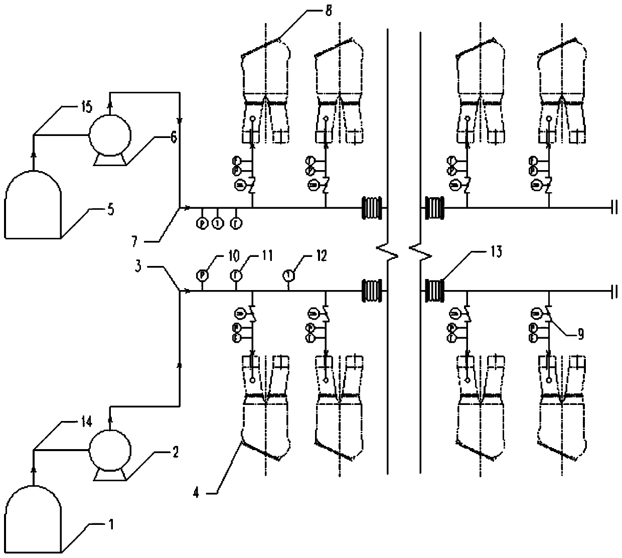
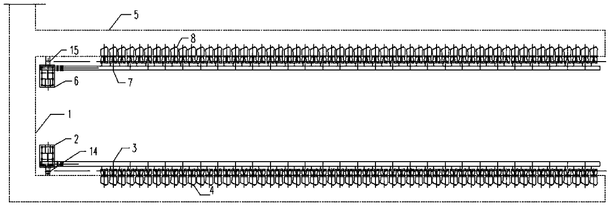
[0058] Such as figure 1 As shown, the main equipment of the flue gas back-distribution system for coke ovens of the present invention includes: coke-side back-distribution fan 2, coke-side back-distribution fan inlet flue 14, coke-side back-distribution fan outlet flue 3, machine-side return Equipped with fan 6, machine-side matched fan inlet flue 15 and machine-side matched fan outlet flue 7. The inlet flue 14 of the coke-side distribution fan connects the inlet of the coke-side distribution fan 2 to the coke-side sub-flue 1, and the outlet flue 3 of the coke-side distribution fan connects the outlet of the coke-side distribution fan 2 to the coke side. The switch 4 is connected, the compensator 13, the pressure gauge 10, the flow meter 11 and the thermometer 12 are arranged on the outlet flue 3 of the coke-side matching fan, and the outlet flue 3 of the coke-side matching fan is opened and closed on the coke side. A regulating valve 9, a pressure gauge 10 and a flow meter 11 ...
PUM
 Abstract
Description
Claims
Application Information