Cooling type spray nozzle and reactor
A reactor and nozzle technology, applied in the field of gasification, can solve the problems of lowering the temperature of the hot fuel, increasing the cost, not meeting the specifications of the oxygen pipeline, etc., and achieving the effect of less temperature loss and less impact
- Summary
- Abstract
- Description
- Claims
- Application Information
AI Technical Summary
Problems solved by technology
Method used
Image

Examples
Embodiment 1
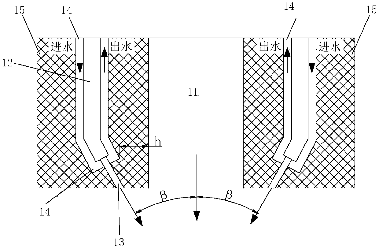
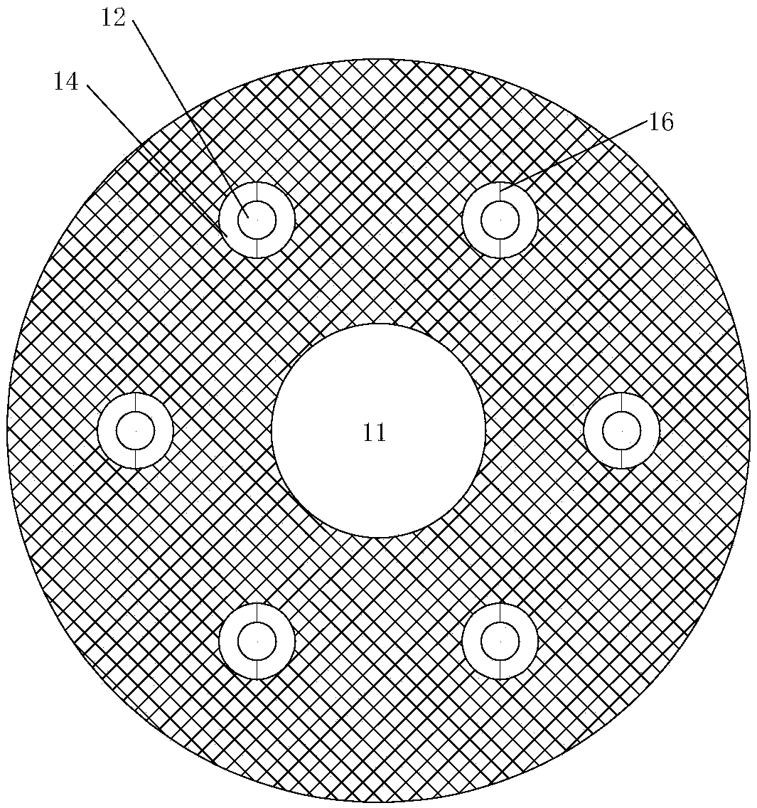
[0075] Such as figure 1 and figure 2 As shown, the nozzle includes a nozzle body, a hot fuel passage 11 , a gasification agent inlet passage 12 , a gasification agent outlet passage 13 , a cooling passage 14 , a cooling passage partition 16 and a refractory insulation layer 15 . Wherein, the nozzle main body is configured to be cylindrical, as shown in the hatched part in the figure; the hot fuel channel 11 is arranged at the center of the nozzle main body, and is used for sending hot fuel into the gasifier; the gasification agent inlet channel 12 and the gasifier The gasifying agent outlet passages 13 jointly constitute the gasifying agent passages, which communicate with each other and are arranged in the nozzle body, the gasifying agent inlet passages 12 are evenly distributed around the hot fuel passage 11, and their inlet ends communicate with the gasifying agent source; gasification The inlet end of the agent outlet passage 13 is connected with the outlet end of the ga...
Embodiment 2
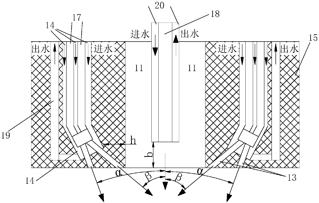
[0088] The main difference between this embodiment and Embodiment 1 is that the gasification agent inlet channel is divided into a circumferential gasification agent inlet channel 17 and a central gasification agent inlet channel 18; The source is connected, a plurality of circumferential gasification agent inlet channels 17 and a cooling channel 14 form a gasification agent-cooling channel group, and the gasification agent-cooling channel group is evenly distributed around the hot fuel channel 11; the gasification agent outlet channel The number of 13 is greater than the number of circumferential gasification agent inlet channels 17; the inlet end of the cooling channel 14 outside the circumferential gasification agent inlet channel 17 is connected to the source of the cooling medium, and the outlet end is connected to the cooling medium outlet channel 19, The cooling medium enters from the inlet end of the cooling channel 14 and leaves the nozzle through the cooling medium ou...
Embodiment 3
[0097] The main difference between this embodiment and Embodiment 1 is that the central gasification agent channel 22 is added as an additional gasification agent channel, and the two ends of the central gasification agent channel 22 are connected to the two gasification agent inlet channels 12 respectively. And across the hot fuel passage 11 , the part of the central gasification agent passage 22 crossing the hot fuel passage 11 is arranged with a central gasification agent outlet 23 , which communicates with the hot fuel passage 11 . With the above structure, the mixing of the gasification agent and the thermal fuel is enhanced.
[0098] Such as Figure 5-Figure 7 As shown, the nozzle includes a hot fuel passage 11 , a gasification agent inlet passage 12 , a central gasification agent passage 22 , a gasification agent outlet passage 13 , a cooling passage 14 and a refractory insulation layer 15 . Among them, the hot fuel passage 11 is used to send hot fuel into the gasifier...
PUM
 Abstract
Description
Claims
Application Information