Wireless charging device, system and method, mobile terminal and storage medium

A wireless charging and charging system technology, applied in circuit devices, battery circuit devices, diversity/multi-antenna systems, etc., can solve the problems of low transmission efficiency, inability to communicate in the cabin, and ensure external wireless communication of energy-receiving devices, and achieve transmission High efficiency and stable transmission effect

Active Publication Date: 2020-06-16
UNIV OF ELECTRONIC SCI & TECH OF CHINA
View PDF4 Cites 2 Cited by
  • Summary
  • Abstract
  • Description
  • Claims
  • Application Information

AI Technical Summary

Problems solved by technology

In 2017, Master Yang Yuan of the University of Electronic Science and Technology of China applied the adaptive focusing technology based on the principle of reciprocity to the field of microwave wireless energy transmission, proving the feasibility of adaptive focusing energy transmission, but it faces open space, so the transmission efficiency remains the same. lower
[0004] Most of the existing microwave radiative energy transfer methods are concerned with focusing at a certain point in free space. There is little electromagnetic transmission in complex environments. Most of the research focuses on focal length, focal spot size, focusing antenna or antenna array. Design, through the optimization of parameters to maximize the efficiency of energy transmission, even if it is used in the fie

Method used


Image

  • Wireless charging device, system and method, mobile terminal and storage medium
  • Wireless charging device, system and method, mobile terminal and storage medium
  • Wireless charging device, system and method, mobile terminal and storage medium

Examples


Example Embodiment

[0056] In order to make the objectives, technical solutions and advantages of the present invention clearer, the present invention will be further described in detail below in conjunction with embodiments. It should be understood that the specific embodiments described herein are only used to explain the present invention, but not to limit the present invention.

[0057] In view of the problems in the prior art, the present invention provides a wireless charging method, system, storage medium, device, and mobile device. The present invention will be described in detail below with reference to the accompanying drawings.

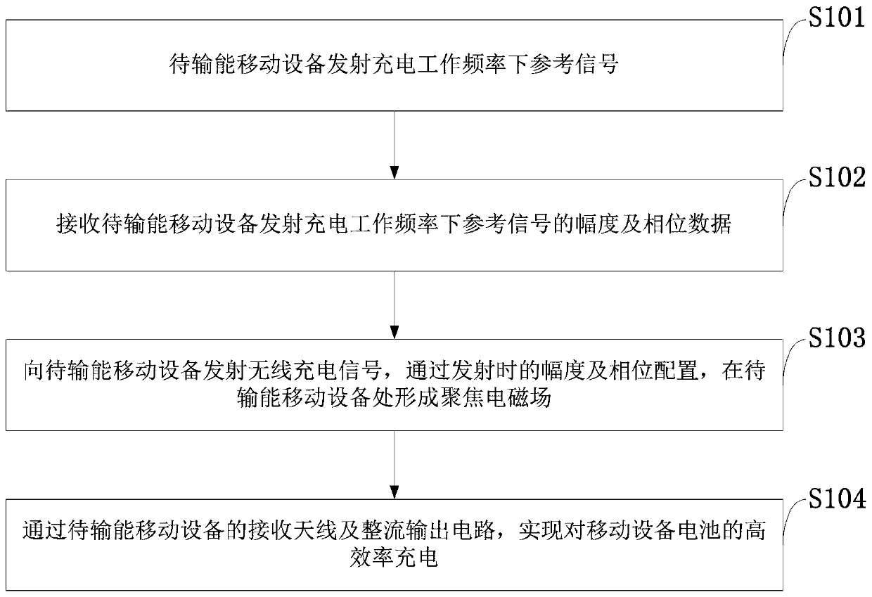
[0058] Such as figure 1 As shown, the wireless charging method provided by the embodiment of the present invention includes the following steps:

[0059] S101: The mobile device to be powered transmits a reference signal at the charging operating frequency;

[0060] S102: Receive the amplitude and phase data of the reference signal at the charging operating frequency ...


PUM


Abstract

The invention belongs to the technical field of wireless charging, and discloses a wireless charging device, system and method, a mobile terminal and a storage medium. The wireless charging device comprises an internal charging system which is installed in an external metal frequency selection box body and used for achieving wireless charging. The four side faces and the top face of the metal frequency selection box body are all band-pass type frequency selection surfaces. A multi-antenna subsystem of the internal charging system comprises N antenna units, wherein N is an integer greater than1. The antenna unit adopts an oscillator antenna, a microstrip patch antenna, a waveguide slot antenna, a spiral antenna or a dielectric resonator antenna; and the N antenna units of the multi-antennasubsystem are uniformly arranged on the inner sides of the four side surfaces of the metal frequency selection box body in a two-dimensional annular manner or are arranged on the three-dimensional curved surface of the whole inner side of the metal frequency selection box body. According to the invention, simultaneous wireless charging of a plurality of mobile communication devices with differentbrands, different device types and different placement modes can be realized, normal communication can be realized, and the device has the advantages of high transmission efficiency, stable transmission, environmental protection and the like.

Description

technical field [0001] The invention belongs to the technical field of wireless charging, and in particular relates to a wireless charging device, system, method, mobile terminal, and storage medium. Background technique [0002] At present, the wireless energy transmission device mainly refers to the wireless energy transmission between the transmitting end and the receiving end by using electromagnetic induction, magnetic coupling resonance, microwave, laser and other non-contact methods without relying on traditional power supply lines. Nowadays, with the development of new media, information technology, Internet and interactive resources, more and more types of mobile devices are being developed, and their functions are also showing a trend of diversification. However, due to the limitation of technical level and design space reserved for devices, A mobile device (mobile device: also known as a mobile device, mobile device, handheld device, etc., is a pocket-sized comput...

Claims


Application Information

Patent Timeline
IPC IPC(8): H02J7/00H02J50/20H04B5/00H04B7/02H04B7/10
CPCH02J50/20H04B5/0037H04B7/02H04B7/10H02J50/23H02J50/402H02J50/005H02J7/0044H02J50/80H02J2310/22H02J50/40H01Q1/243H01Q9/0407
Inventor 宗显政聂在平熊文胡俊杨仕文叶旭宇阙肖峰陈涌频
Owner UNIV OF ELECTRONIC SCI & TECH OF CHINA
Why Eureka
Try Eureka