
Accurate cutting temperature measuring device for turn-milling machining

A cutting temperature and accurate technology, applied in measuring devices, components using electrical devices, thermometers, etc., can solve the problems of discontinuous signal acquisition, inconvenient installation of thermocouples, and unsuitable coating tools.

Pending Publication Date: 2020-06-19
XUZHOU UNIV OF TECH
View PDF0 Cites 6 Cited by
  • Summary
  • Abstract
  • Description
  • Claims
  • Application Information

AI Technical Summary

Problems solved by technology

Among them, the thermocouple method is the most accurate measurement method, but for turning and milling processing, due to the common rotation of the milling cutter and the workpiece, the thermocouple method for turning and milling has technical difficulties in the installation of thermocouples.
At present, there are few technologies involving turning and milling temperature measurement. Among them, the patent number: ZL2013104102758, the invention patent named "Cutting Temperature Measuring Device for Turning and Milling Composite Machining" uses the natural thermocouple method to measure the average temperature of the processing area. It needs to calibrate the tool material, which increases the production process of the calibration sample, and is only suitable for single-material tools, not for coated tools; in addition, the paper "An Investigation of Workpiece Temperature in Orthogonal Turn-Milling Compound Machining" (Journal of Manufacturing Science and Engineering, 2015, 137(1): 1-10) The temperature measurement method used requires difficult sample processing, and the discontinuity of the acquisition signal terminal will cause large fluctuations in the collected signal

Method used


Image

  • Accurate cutting temperature measuring device for turn-milling machining
  • Accurate cutting temperature measuring device for turn-milling machining
  • Accurate cutting temperature measuring device for turn-milling machining

Examples


Embodiment Construction

[0019] The present invention will be further described below.

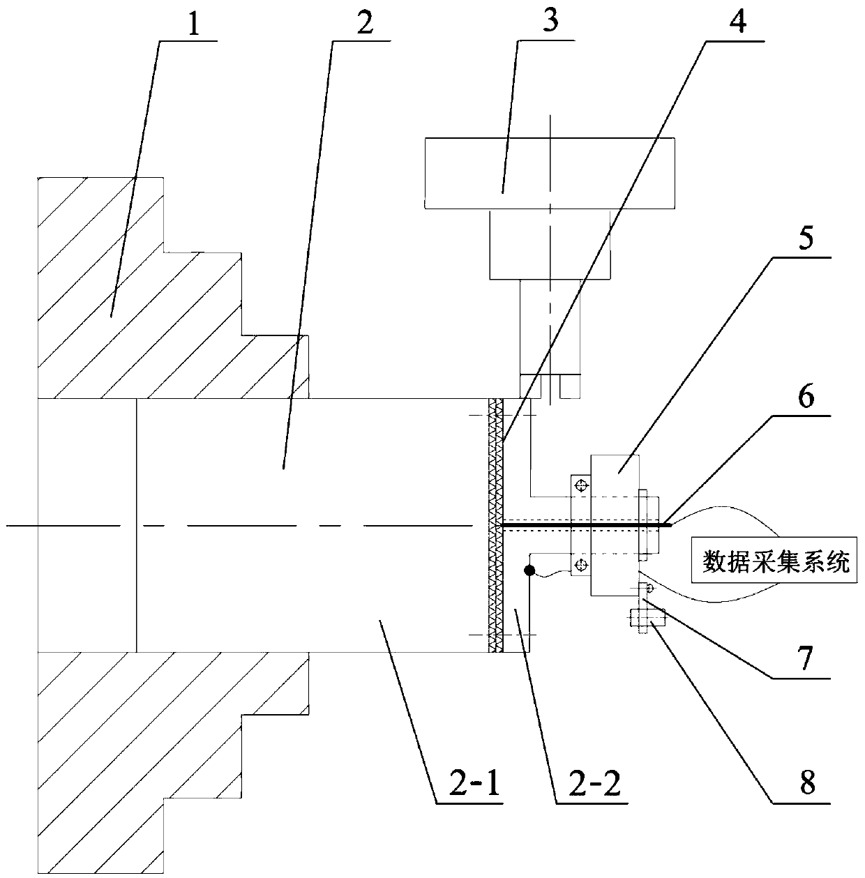
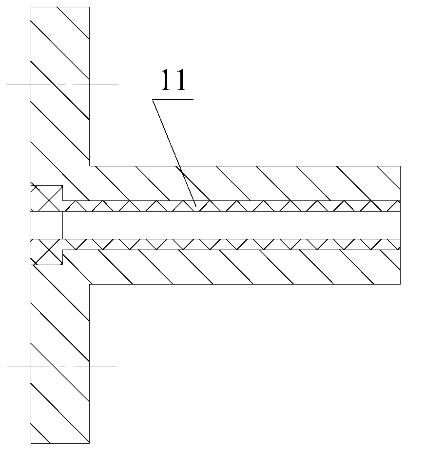
[0020] like Figure 1 to Figure 5 As shown, the present invention includes a workpiece temperature measurement sample 2, a conductive slip ring 5, a plurality of thermocouple wires 6, a cylindrical insulating tube 11, a fixed bracket and a data acquisition system,

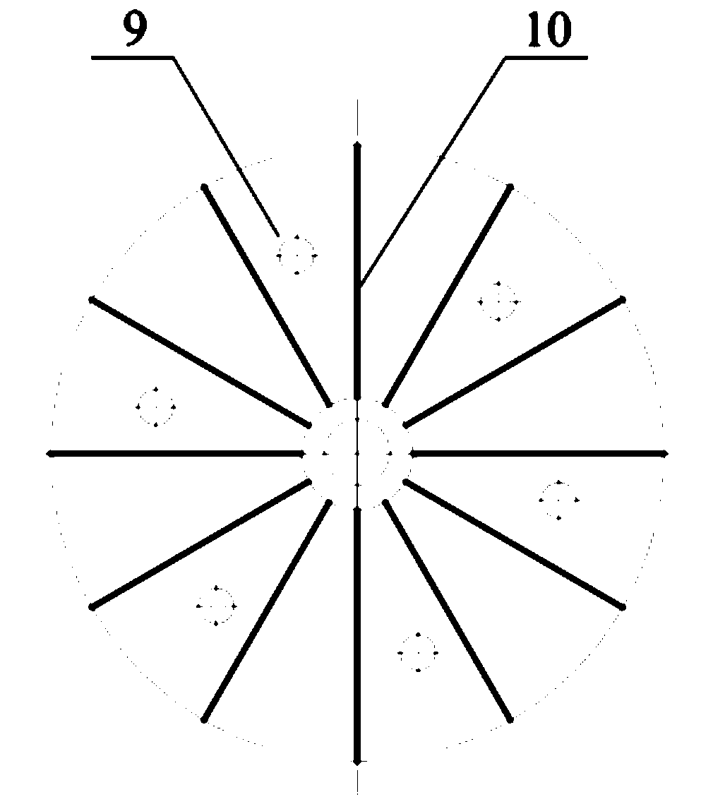
[0021] The workpiece temperature measurement sample 2 is composed of part I2-1 and part II2-2, the materials of part I2-1 and part II2-2 are the same, the shape of part I2-1 is cylindrical, and the shape of part II2-2 is A hollow shaft with a disk 9 at one end, the diameter of the disk 9 of the part II2-2 is the same as that of the part I2-1, and a plurality of grooves 10 are opened on one end of the disk 9 of the part II2-2, each groove 10 The two ends are respectively connected with one end of the hollow shaft in the center of the disc 9 and the outer edge of the disc 9, and the cylindrical insulating tube 11 is inserted into and fixed in the hollow...


PUM


Abstract

The invention discloses an accurate cutting temperature measuring device for turn-milling machining. The device comprises a workpiece temperature measuring sample, a conductive slip ring, a pluralityof thermocouple wires, a cylindrical insulating tube, a fixing bracket and a data acquisition system. The workpiece temperature measuring sample is prepared from a material the same as that of a workpiece to be turned and milled; during turning and milling, when a cutting edge of a milling cutter passes through a joint between a component I and a component II, one end of each thermocouple wire iselectrically connected with the workpiece temperature measuring sample to form an instantaneous hot joint, which forms a hot end of a thermocouple; the other end of the thermocouple wires and a point,close to a hollow shaft, on a disc forms a cold end of the thermocouple; that is, at this time, the workpiece temperature measuring sample, the conductive slip ring and the plurality of thermocouplewires form the thermocouple; finally, the current cutting temperature is measured; and corresponding different cutting temperatures can be accurately measured by adjusting different turning and milling parameters, and thus, optimal turning and milling parameters of the material are determined finally. Therefore, machining efficiency and machining surface quality are effectively improved, and the service life of the cutter is effectively prolonged.

Description

technical field [0001] The invention relates to a device for measuring cutting temperature, in particular to a device for accurately measuring cutting temperature in turning and milling. Background technique [0002] Turning and milling machining completes the efficient and precise machining of shaft parts through the common rotation of the milling cutter and the workpiece and the movement of the milling cutter. Now it has been widely used in difficult-to-machine materials in the aerospace field (such as: titanium alloys, high-temperature alloys, stainless steel, etc.) And the processing of special structural parts (such as: slender rods, receivers, landing gear, etc.). [0003] Compared with the continuous cutting of turning, the characteristics of intermittent cutting in turning and milling can help reduce the cutting temperature, thereby improving tool life and machined surface quality, which is also an important reason why turning and milling are widely used in cutting d...

Claims


Application Information

Patent Timeline
IPC IPC(8): B23Q17/00B23Q17/09
CPCB23Q17/00B23Q17/0904B23Q17/0985G01K1/026G01K7/02G01K13/08
Inventor 孙涛秦录芳王海王锦超
Owner XUZHOU UNIV OF TECH
Learn More